Subaru Crosstrek Service Manual: Dtc p0223 throttle/pedal position sensor/switch "b" circuit high
ENGINE (DIAGNOSTICS)(H4DO) > Diagnostic Procedure with Diagnostic Trouble Code (DTC)
DTC P0223 THROTTLE/PEDAL POSITION SENSOR/SWITCH "B" CIRCUIT HIGH
DTC detecting condition:
Immediately at fault recognition
Trouble symptom:
• Improper idling
• Poor driving performance
• Engine stall
CAUTION:
After servicing or replacing faulty parts, perform Clear Memory Mode Clear Memory Mode > OPERATION"> , and Inspection Mode Inspection Mode > PROCEDURE">.
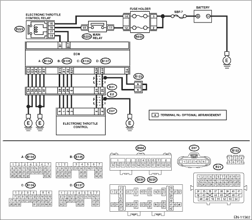
Wiring diagram:
Engine electrical system Engine Electrical System">
| STEP | CHECK | YES | NO |
1.CHECK HARNESS BETWEEN ECM AND ELECTRONIC THROTTLE CONTROL CONNECTOR.
1) Turn the ignition switch to OFF.
2) Disconnect the connector from ECM.
3) Disconnect the connectors from electronic throttle control.
4) Measure the resistance of harness between ECM connector and electronic throttle control connector.
Connector & terminal
(B134) No. 28 — (E57) No. 4:
(B134) No. 29 — (E57) No. 3:
Is the resistance less than 1 ??
Diagnostic Procedure with Diagnostic Trouble Code (DTC) > DTC P0223 THROTTLE/PEDAL POSITION SENSOR/SWITCH "B" CIRCUIT HIGH">Go to Step 2.
Repair the harness and connector.
NOTE:
In this case, repair the following item:
• Open circuit in harness between ECM connector and electronic throttle control connector
• Poor contact of coupling connector
2.CHECK HARNESS BETWEEN ECM AND ELECTRONIC THROTTLE CONTROL CONNECTOR.
1) Connect the connector to ECM.
2) Measure the resistance between electronic throttle control connector and engine ground.
Connector & terminal
(E57) No. 3 — Engine ground:
Is the resistance less than 5 ??
Diagnostic Procedure with Diagnostic Trouble Code (DTC) > DTC P0223 THROTTLE/PEDAL POSITION SENSOR/SWITCH "B" CIRCUIT HIGH">Go to Step 3.
Repair the harness and connector.
NOTE:
In this case, repair the following item:
• Open circuit of harness between ECM connector and engine ground
• Poor contact of ECM connector
• Poor contact of coupling connector
3.CHECK HARNESS BETWEEN ECM AND ELECTRONIC THROTTLE CONTROL CONNECTOR.
1) Turn the ignition switch to ON.
2) Measure the voltage between electronic throttle control connector and engine ground.
Connector & terminal
(E57) No. 4 (+) — Engine ground (−):
Is the voltage 5 V or more?
Repair the short circuit to power in the harness between ECM connector and electronic throttle control connector.
Diagnostic Procedure with Diagnostic Trouble Code (DTC) > DTC P0223 THROTTLE/PEDAL POSITION SENSOR/SWITCH "B" CIRCUIT HIGH">Go to Step 4.
4.CHECK HARNESS BETWEEN ECM AND ELECTRONIC THROTTLE CONTROL CONNECTOR.
1) Turn the ignition switch to OFF.
2) Disconnect the connector from ECM.
3) Measure the resistance between ECM connectors.
Connector & terminal
(B134) No. 19 — (B134) No. 28:
Is the resistance 1 M? or more?
Repair the poor contact of electronic throttle control connector. Replace the electronic throttle control if defective. Throttle Body">
Repair the short circuit to power in the harness between ECM connector and electronic throttle control connector.
1. OUTLINE OF DIAGNOSIS
Detect the open or short circuit of throttle position sensor 2.
Judge as NG if out of specification.
2. COMPONENT DESCRIPTION
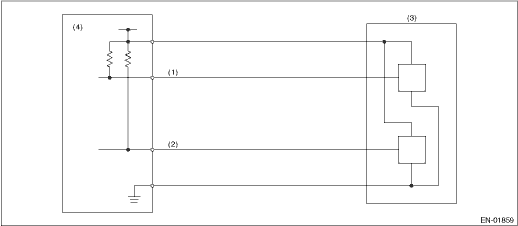
(1) | Throttle position sensor 1 signal | (3) | Throttle position sensor | (4) | Engine control module (ECM) |
(2) | Throttle position sensor 2 signal |
3. EXECUTION CONDITION
Secondary Parameters | Execution condition |
Battery voltage | ≥ 6 V |
4. GENERAL DRIVING CYCLE
Always perform the diagnosis continuously.
5. DIAGNOSTIC METHOD
If the duration of time while the following conditions are met is longer than the time indicated, judge as NG.
Malfunction Criteria | Threshold Value |
Sensor 2 input voltage | ≥ 4.772 V |
Time Needed for Diagnosis: 24 ms
Malfunction Indicator Light Illumination: Illuminates as soon as a malfunction occurs.
 Dtc p0222 throttle/pedal position sensor/switch "b" circuit low
ENGINE (DIAGNOSTICS)(H4DO) > Diagnostic Procedure with Diagnostic Trouble Code (DTC)DTC P0222 THROTTLE/PEDAL POSITION SENSOR/SWITCH "B" CIRCUIT LOWDTC detecting condition:Immediately at f ...
 Dtc p0300 random/multiple cylinder misfire detected
ENGINE (DIAGNOSTICS)(H4DO) > Diagnostic Procedure with Diagnostic Trouble Code (DTC)DTC P0300 RANDOM/MULTIPLE CYLINDER MISFIRE DETECTEDDTC DETECTING CONDITION:• Detected when two consecutive ...
Other materials:
Operation
Blind Spot Detection/Rear Cross Traffic Alert (DIAGNOSTICS) > System Operation Check ModeOPERATION1. On «Start» display, select «Diagnosis».2. On «Vehicle selection» display, input the target vehicle information and select «Confirmed».3. On «Main Menu» display, select «Each System».4. ...
Third-row seats
In the Subaru Ascent, all third-row seating positions are equipped with head
restraints designed to enhance passenger protection and comfort. These head restraints
can be adjusted easily to ensure proper support and optimal safety during travel.
When not used (retracted position)
When ...
Disassembly
FUEL INJECTION (FUEL SYSTEMS)(H4DO) > Intake ManifoldDISASSEMBLY1. Remove the throttle body. Throttle Body > REMOVAL">2. Remove the purge control solenoid valve. Purge Control Solenoid Valve > REMOVAL">3. Remove the manifold absolute pressure sensor. Manifold Absolute Pre ...
