Subaru Crosstrek Service Manual: Dtc p0134 a/f / o2 sensor circuit no activity detected bank 1 sensor 1
ENGINE (DIAGNOSTICS)(H4DO) > Diagnostic Procedure with Diagnostic Trouble Code (DTC)
DTC P0134 A/F / O2 SENSOR CIRCUIT NO ACTIVITY DETECTED BANK 1 SENSOR 1
DTC detecting condition:
Immediately at fault recognition
CAUTION:
After servicing or replacing faulty parts, perform Clear Memory Mode Clear Memory Mode > OPERATION"> , and Inspection Mode Inspection Mode > PROCEDURE">.
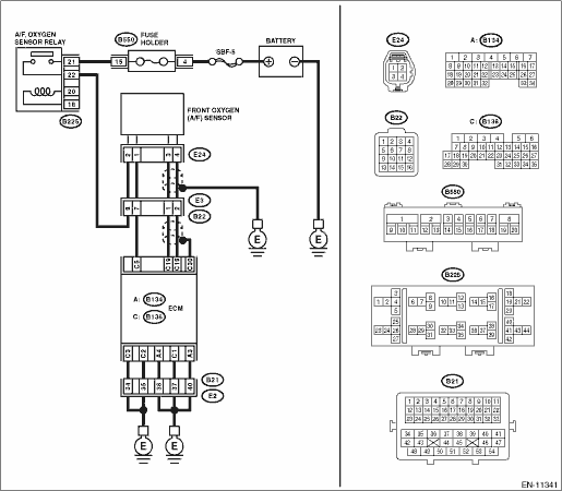
Wiring diagram:
Engine electrical system Engine Electrical System">
| STEP | CHECK | YES | NO |
1.CHECK HARNESS BETWEEN ECM AND FRONT OXYGEN (A/F) SENSOR CONNECTOR.
1) Turn the ignition switch to OFF.
2) Disconnect the connector from ECM.
3) Disconnect the connectors from front oxygen (A/F) sensor.
4) Measure the resistance of harness between ECM connector and front oxygen (A/F) sensor connector.
Connector & terminal
(B136) No. 19 — (E24) No. 3:
(B136) No. 18 — (E24) No. 4:
Is the resistance less than 1 ??
Diagnostic Procedure with Diagnostic Trouble Code (DTC) > DTC P0134 A/F / O2 SENSOR CIRCUIT NO ACTIVITY DETECTED BANK 1 SENSOR 1">Go to Step 2.
Repair the harness and connector.
NOTE:
In this case, repair the following item:
• Open circuit in harness between ECM connector and front oxygen (A/F) sensor connector
• Poor contact of coupling connector
2.CHECK FOR POOR CONTACT.
Check for poor contact of ECM and front oxygen (A/F) sensor connector.
Is there poor contact of ECM or front oxygen (A/F) sensor connector?
Repair the poor contact of ECM or front oxygen (A/F) sensor connector.
Replace the front oxygen (A/F) sensor. Front Oxygen (A/F) Sensor">
1. OUTLINE OF DIAGNOSIS
Detect open circuits of the sensor.
Judge as NG when the impedance of the element is large.
2. COMPONENT DESCRIPTION
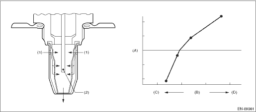
(A) | Electromotive force | (B) | Air fuel ratio | (C) | Rich |
(D) | Lean | ||||
(1) | Exhaust gas | (2) | Zirconia element oxygen |
3. EXECUTION CONDITION
Secondary Parameters | Execution condition |
Battery voltage | ≥ 10.9 V |
Time of heater control duty at 70 % or more | ≥ 36000 ms |
4. GENERAL DRIVING CYCLE
Always perform the diagnosis continuously.
5. DIAGNOSTIC METHOD
If the duration of time while the following conditions are met is longer than the time indicated, judge as NG.
Malfunction Criteria | Threshold Value |
Front oxygen (A/F) sensor impedance | > 450 ? |
Time Needed for Diagnosis: 5000 ms
Malfunction Indicator Light Illumination: Illuminates as soon as a malfunction occurs.
 Dtc p0132 a/f / o2 sensor circuit high voltage bank 1 sensor 1
ENGINE (DIAGNOSTICS)(H4DO) > Diagnostic Procedure with Diagnostic Trouble Code (DTC)DTC P0132 A/F / O2 SENSOR CIRCUIT HIGH VOLTAGE BANK 1 SENSOR 1DTC DETECTING CONDITION:Immediately at fault recogn ...
 Dtc p0137 o2 sensor circuit low voltage bank 1 sensor 2
ENGINE (DIAGNOSTICS)(H4DO) > Diagnostic Procedure with Diagnostic Trouble Code (DTC)DTC P0137 O2 SENSOR CIRCUIT LOW VOLTAGE BANK 1 SENSOR 2DTC detecting condition:Detected when two consecutive driv ...
Other materials:
Inspection
CONTINUOUSLY VARIABLE TRANSMISSION(TR580) > Transmission HarnessINSPECTION1. Visually check the harness and connector for damage or crack.2. Check the harness terminal for rust, disconnection or poor contact.3. Check the continuity between harness terminals.NOTE:For details of transmission harnes ...
Dtc b2277 submerging circuit
KEYLESS ACCESS WITH PUSH BUTTON START SYSTEM (DIAGNOSTICS) > Diagnostic Procedure with Diagnostic Trouble Code (DTC)DTC B2277 SUBMERGING CIRCUITDTC detecting condition:When the water-submersion detection circuit integrated into the keyless access CM detects the water submersion.Trouble symptom:&b ...
Procedure
LAN SYSTEM (DIAGNOSTICS) > CAN Communication Circuit CheckPROCEDURENOTE:• When measuring the resistance of CAN communication circuit, measure it in sleep status.To enter sleep status– With ignition switch OFF and key or switch operation stopped, keep the doors, trunk, and rear gate all c ...
