Subaru Crosstrek Service Manual: Procedure
LAN SYSTEM (DIAGNOSTICS) > CAN Communication Circuit Check
PROCEDURE
NOTE:
• When measuring the resistance of CAN communication circuit, measure it in sleep status.
To enter sleep status
– With ignition switch OFF and key or switch operation stopped, keep the doors, trunk, and rear gate all closed for one minute or more.
– On models with keyless access function, keep the access key 2 m or more away from the vehicle.
• When the bus line is measured, combined resistance of the end resistance (120 ?) in ECM and the end resistance (120 ?) in VDC CM can be measured. The combined resistance is supposed to be approximately 53 — 61 ? with the stabilizing circuit included. If the measured resistance value becomes 52 ? or less, main wiring harness or related lines may be shorted. Or, the combined resistance may have changed because of a resistance other than the end resistance created on the circuit. If the measured value is 62 ? or more, there may be a malfunction such as open circuit in one of the end resistances, in the stabilizing circuit, or in the main wiring harness.
Also, even when the resistance value falls within approx. 53 — 61 ?, related lines may be open if an error of communication for initializing or a CAN system U-code has occurred. (The resistance cannot be between approx. 53 — 61 ? if the main wiring harness is open.)
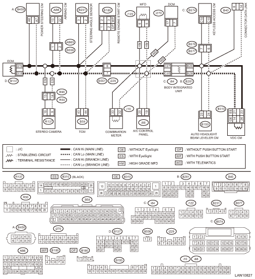
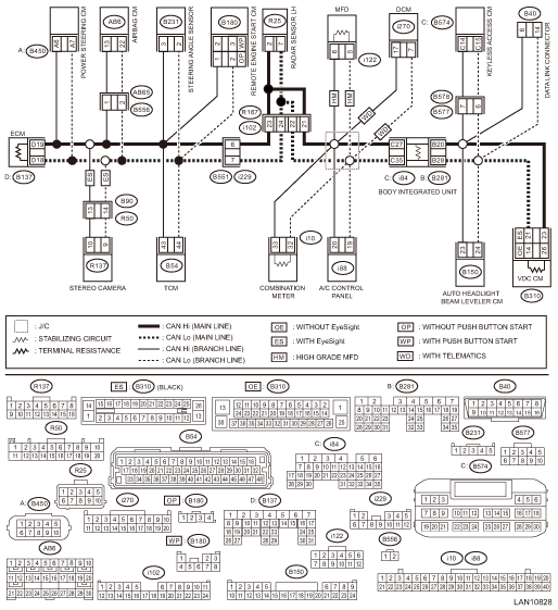
Wiring diagram:
CAN communication system CAN Communication System > WIRING DIAGRAM">
• Without BSD/RCTA
• With BSD/RCTA
| STEP | CHECK | YES | NO |
1.CHECK BASIC DIAGNOSTIC PROCEDURE.
Check that the basic diagnosis has been performed up to STEP 3.
NOTE:
Possible defective parts can be narrowed easily by inspection using Subaru Select Monitor before performing “CHECK CAN COMMUNICATION CIRCUIT” using a tester.
Was the basic diagnostic procedure performed?
CAN Communication Circuit Check > PROCEDURE">Go to Step 2.
Perform the basic diagnostic procedure. Basic Diagnostic Procedure > PROCEDURE">
2.CHECK FROM DATA LINK CONNECTOR.
Using the tester, measure the resistance between terminals.
Connector & terminal
(B40) No. 6 — Chassis ground:
(B40) No. 14 — Chassis ground:
Is the resistance less than 10 ??
Check for ground short. CAN Communication Circuit Check > INSPECTION">
CAN Communication Circuit Check > PROCEDURE">Go to Step 3.
3.CHECK FROM DATA LINK CONNECTOR.
1) Turn the ignition switch to ON.
2) Using the tester, measure the voltage between terminals.
Connector & terminal
(B40) No. 6 — Chassis ground:
(B40) No. 14 — Chassis ground:
Is the voltage 5 V or less?
CAN Communication Circuit Check > PROCEDURE">Go to Step 4.
Check for battery short. CAN Communication Circuit Check > INSPECTION">
4.CHECK FROM DATA LINK CONNECTOR.
1) Turn the ignition switch to OFF.
2) Using the tester, measure the resistance between terminals.
Connector & terminal
(B40) No. 6 — No. 14:
Is the resistance 52 ? or less?
Perform the inspection for resistance of 52 ? or less. CAN Communication Circuit Check > INSPECTION">
CAN Communication Circuit Check > PROCEDURE">Go to Step 5.
5.CHECK FROM DATA LINK CONNECTOR.
Using the tester, measure the resistance between terminals.
Connector & terminal
(B40) No. 6 — No. 14:
Is the resistance 62 ? or more?
Perform the inspection for resistance of 62 ? or more. CAN Communication Circuit Check > INSPECTION">
If the display of CAN system U-code disappears from the current malfunction, the CAN network is currently normal. If the U-code has detected as current malfunction, related lines may be open. Perform the inspection for the related line corresponding to the detected DTC. CAN Communication Circuit Check > LIST">
 Inspection
LAN SYSTEM (DIAGNOSTICS) > CAN Communication Circuit CheckINSPECTION1. GROUND SHORT INSPECTIONWiring diagram:CAN communication system CAN Communication System > WIRING DIAGRAM">• ...

Other materials:
Component
HVAC SYSTEM (HEATER, VENTILATOR AND A/C) > General DescriptionCOMPONENT1. HEATER AND COOLING UNIT• Manual A/C model(1)Pipe - inlet(11)Shutter - defroster(21)Packing - evaporator core(2)Pipe - outlet(12)Shutter - vent(22)Pipe - evaporator core(3)Clamp - pipe(13)Shutter - air mix RH(23)Case - ...
Clear memory mode Operation
Blind Spot Detection/Rear Cross Traffic Alert (DIAGNOSTICS) > Clear Memory ModeOPERATION1. On «Start» display, select «Diagnosis».2. On «Vehicle selection» display, input the target vehicle information and select «Confirmed».3. On «Main Menu» display, select «Each System».4. On «Sele ...
Assembly
SEATS > Rear SeatASSEMBLYCAUTION:• Do not reuse hog rings.• Secure the hog ring using hog ring pliers.• Install the hog rings to the specified points securely and make sure that there is no wrinkle or twisting on the cover COMPL - rear backrest.1. Assemble the cover COMPL - rear ...
