Subaru Crosstrek Service Manual: Dtc p0103 mass or volume air flow sensor "a" circuit high
ENGINE (DIAGNOSTICS)(H4DO) > Diagnostic Procedure with Diagnostic Trouble Code (DTC)
DTC P0103 MASS OR VOLUME AIR FLOW SENSOR "A" CIRCUIT HIGH
DTC detecting condition:
Immediately at fault recognition
Trouble symptom:
• Improper idling
• Engine stall
• Poor driving performance
CAUTION:
After servicing or replacing faulty parts, perform Clear Memory Mode Clear Memory Mode > OPERATION"> , and Inspection Mode Inspection Mode > PROCEDURE">.
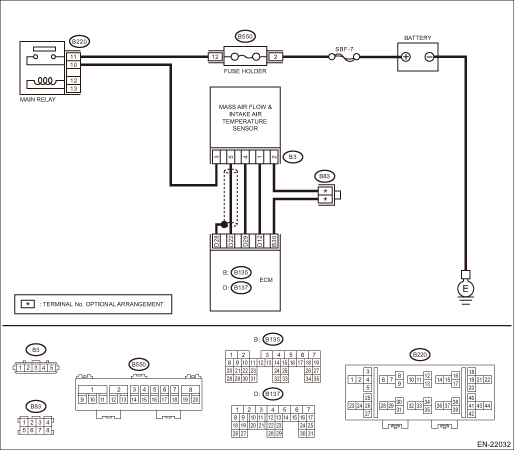
Wiring diagram:
Engine electrical system Engine Electrical System">
| STEP | CHECK | YES | NO |
1.CHECK CURRENT DATA.
1) Start the engine.
2) Read the value of «Air Flow Sensor Voltage» using Subaru Select Monitor.
NOTE:
For detailed operation procedures, refer to “Current Data Display For Engine”. Subaru Select Monitor">
Is the value of «Air Flow Sensor Voltage» 5 V or more?
Diagnostic Procedure with Diagnostic Trouble Code (DTC) > DTC P0103 MASS OR VOLUME AIR FLOW SENSOR "A" CIRCUIT HIGH">Go to Step 2.
Even if DTC is detected, the circuit has returned to a normal condition at this time. Reproduce the failure, and then perform the diagnosis again.
NOTE:
In this case, temporary poor contact of connector, temporary open or short circuit of harness may be the cause.
2.CHECK HARNESS BETWEEN ECM AND MASS AIR FLOW AND INTAKE AIR TEMPERATURE SENSOR CONNECTOR.
1) Turn the ignition switch to OFF.
2) Disconnect the connectors from the mass air flow and intake air temperature sensor.
3) Start the engine.
4) Read the value of «Air Flow Sensor Voltage» using Subaru Select Monitor.
NOTE:
For detailed operation procedures, refer to “Current Data Display For Engine”. Subaru Select Monitor">
Is the value of «Air Flow Sensor Voltage» 5 V or more?
Repair the short circuit of harness to power supply between ECM connector and the mass air flow and intake air temperature sensor connector.
Diagnostic Procedure with Diagnostic Trouble Code (DTC) > DTC P0103 MASS OR VOLUME AIR FLOW SENSOR "A" CIRCUIT HIGH">Go to Step 3.
3.CHECK HARNESS BETWEEN ECM AND MASS AIR FLOW AND INTAKE AIR TEMPERATURE SENSOR CONNECTOR.
1) Turn the ignition switch to OFF.
2) Measure the resistance of harness between mass air flow and intake air temperature sensor connector and engine ground.
Connector & terminal
(B3) No. 4 — Engine ground:
Is the resistance less than 5 ??
Diagnostic Procedure with Diagnostic Trouble Code (DTC) > DTC P0103 MASS OR VOLUME AIR FLOW SENSOR "A" CIRCUIT HIGH">Go to Step 4.
Repair the harness and connector.
NOTE:
In this case, repair the following item:
• Open circuit in harness between ECM connector and the mass air flow and intake air temperature sensor connector
• Poor contact of ECM connector
4.CHECK FOR POOR CONTACT.
Check for poor contact of mass air flow and intake air temperature sensor connector.
Is there poor contact of mass air flow and intake air temperature sensor connector?
Repair the poor contact of mass air flow and intake air temperature sensor connector.
Replace the mass air flow and intake air temperature sensor. Mass Air Flow and Intake Air Temperature Sensor">
1. OUTLINE OF DIAGNOSIS
Detect open or short circuits of the air flow sensor.
Judge as NG if out of specification.
2. COMPONENT DESCRIPTION
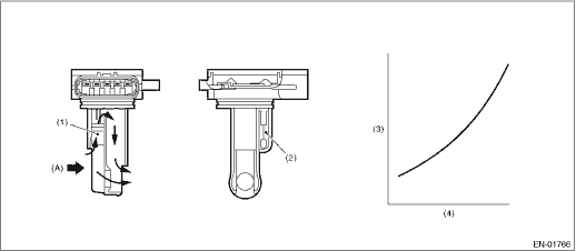
(A) | Air | ||||
(1) | Air flow sensor | (3) | Voltage (V) | (4) | Intake air amount (kg (lb)/s) |
(2) | Intake air temperature sensor |
3. EXECUTION CONDITION
Secondary Parameters | Execution condition |
None |
4. GENERAL DRIVING CYCLE
Always perform the diagnosis continuously.
5. DIAGNOSTIC METHOD
If the duration of time while the following conditions are met is longer than the time indicated, judge as NG.
Malfunction Criteria | Threshold Value |
Output voltage | ≥ 4.43 V |
Time Needed for Diagnosis: 500 ms
Malfunction Indicator Light Illumination: Illuminates as soon as a malfunction occurs.
 Dtc p0102 mass or volume air flow sensor "a" circuit low
ENGINE (DIAGNOSTICS)(H4DO) > Diagnostic Procedure with Diagnostic Trouble Code (DTC)DTC P0102 MASS OR VOLUME AIR FLOW SENSOR "A" CIRCUIT LOWDTC detecting condition:Immediately at fault re ...
 Dtc p0107 manifold absolute pressure/barometric pressure sensor circuit low
ENGINE (DIAGNOSTICS)(H4DO) > Diagnostic Procedure with Diagnostic Trouble Code (DTC)DTC P0107 MANIFOLD ABSOLUTE PRESSURE/BAROMETRIC PRESSURE SENSOR CIRCUIT LOWDTC detecting condition:Immediately at ...
Other materials:
Installation
EXTERIOR/INTERIOR TRIM > Side GarnishINSTALLATIONCAUTION:Do not reuse the garnish assembly. Deformation occurs on the garnish assembly when once removed, and this may cause improper adhesion.1. Install each part in the reverse order of removal.2. Install the garnish assembly - fender and the garn ...
Preparation tool
FRONT SUSPENSION > General DescriptionPREPARATION TOOL1. SPECIAL TOOLILLUSTRATIONTOOL NUMBERDESCRIPTIONREMARKS927680000INSTALLER & REMOVER SETUsed for replacing the bushing front - front arm of front arm assembly.20299AG000REMOVER• Used for replacing the bushing rear - front arm of fron ...
Certification
Bluetooth
The Bluetooth word mark and logo are
registered trademarks of Bluetooth SIG,
Inc. and any use of such marks by Clarion
Co., Ltd. is under license.
SiriusXM Satel l i t e Radio ( i f
equipped)
SiriusXMTM and all related marks and
logos are trademarks of SiriusXM Radio
Inc. All ri ...
