Subaru Crosstrek Service Manual: Assembly
CONTINUOUSLY VARIABLE TRANSMISSION(TR580) > Transfer Clutch
ASSEMBLY
1. Install the transfer clutch piston.
NOTE:
Apply CVTF to the transfer clutch piston lip.
2. Install the return spring.
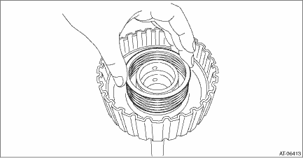
3. Install the transfer clutch piston seal.
NOTE:
Apply CVTF to the lip section of transfer clutch piston seal.
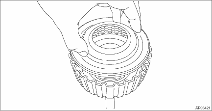
4. Compress the return spring using the ST to install the snap ring.
| ST 18762AA001 | COMPRESSOR SPECIAL TOOL |
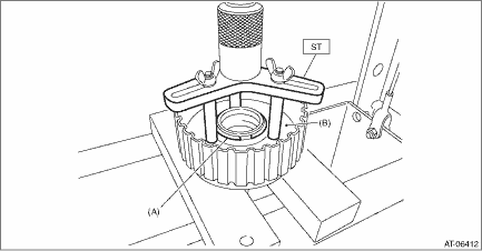
(A) | Snap ring |
(B) | Transfer clutch piston seal |
5. Install the pressure plate, driven plate, drive plate and snap ring.
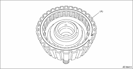
(A) | Snap ring |
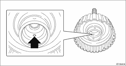
6. Blow compressed air through transfer clutch assembly hole, and check the transfer clutch piston operation.
NOTE:
Plug the holes through which the compressed air is not blown.
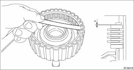
7. Before measuring clearance “A”, place same thickness shims on both sides to prevent the plate from tilting.
8. When the clearance “A” exceeds the limit for use, select the transfer clutch plate set and pressure plate, and adjust the clearance “A” within the initial specified value.
Initial standard:
0.7 — 1.1 mm (0.028 — 0.043 in)
Limit thickness:
1.3 mm (0.051 in)
(1) Measure the thickness of the pressure plate for the transfer clutch plate set that has been used before replacement.
(2) Select the transfer clutch plate set that uses the pressure plate of which the value is close to the measured value in (1), and check the clearance “A”.
Transfer clutch plate set | |
Part No. | Pressure plate thickness mm (in) |
31523AA370 | 3.3 (0.130) |
31523AA380 | 3.7 (0.146) |
31523AA390 | 4.1 (0.161) |
31523AA400 | 4.5 (0.177) |
(3) When the clearance “A” exceeds the limit for use in step (2), replace the pressure plate installed on the lower side of the transfer clutch plate set, and check the clearance “A” again.
Pressure plate | |
Part No. | Thickness mm (in) |
31593AA151 | 3.3 (0.130) |
31593AA161 | 3.7 (0.146) |
(4) When the clearance “A” exceeds the limit for use in step (3), select the transfer clutch plate set that was not used in step (2), and adjust the clearance “A” again.
9. Check the clearance between snap ring and pressure plate. Transfer Clutch > INSPECTION">
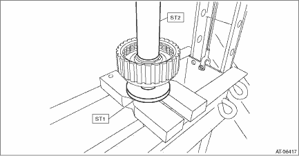
10. Using the ST, install the ball bearing.
NOTE:
Use a new ball bearing.
| ST1 398177700 | INSTALLER |
| ST2 499277000 | INSTALLER |
 Removal
CONTINUOUSLY VARIABLE TRANSMISSION(TR580) > Transfer ClutchREMOVAL1. Remove the transmission assembly from the vehicle. Automatic Transmission Assembly > REMOVAL">2. Remove the extensio ...
 Disassembly
CONTINUOUSLY VARIABLE TRANSMISSION(TR580) > Transfer ClutchDISASSEMBLY1. Remove the snap ring, and then remove the pressure plate, drive plate and driven plate.(A)Snap ring2. Compress the return sp ...
Other materials:
Remote keyless entry system
CAUTION
Do not expose the remote transmitter
to severe shocks, such as
those experienced as a result of
dropping or throwing.
Do not take the remote transmitter
apart except when replacing
the battery
Do not get the remote transmitter
wet. If it gets wet, wipe it dry with
a clo ...
Installation
MECHANICAL(H4DO) > Engine AssemblyINSTALLATION1. Install the engine mounting onto the engine.Tightening torque:35 N·m (3.6 kgf-m, 25.8 ft-lb)2. Apply a small amount of grease to splines of main shaft. (MT model)Grease:NICHIMOLY N-130 or equivalent3. Position the engine in engine compartmen ...
Installation
CONTINUOUSLY VARIABLE TRANSMISSION(TR580) > Control Valve BodyINSTALLATION1. Clean the mating surface of valve cover and transmission side.CAUTION:When cleaning the mating surface of the transmission side, be careful not to allow any dust, foreign matter and used liquid gasket to enter the transm ...
