Subaru Crosstrek Service Manual: Dtc p0107 manifold absolute pressure/barometric pressure sensor circuit low
ENGINE (DIAGNOSTICS)(H4DO) > Diagnostic Procedure with Diagnostic Trouble Code (DTC)
DTC P0107 MANIFOLD ABSOLUTE PRESSURE/BAROMETRIC PRESSURE SENSOR CIRCUIT LOW
DTC detecting condition:
Immediately at fault recognition
CAUTION:
After servicing or replacing faulty parts, perform Clear Memory Mode Clear Memory Mode > OPERATION"> , and Inspection Mode Inspection Mode > PROCEDURE">.
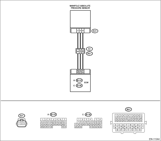
Wiring diagram:
Engine electrical system Engine Electrical System">
| STEP | CHECK | YES | NO |
1.CHECK CURRENT DATA.
1) Start the engine.
2) Read the value of «Mani. Absolute Pressure» using the Subaru Select Monitor or a general scan tool.
NOTE:
• Subaru Select Monitor
For detailed operation procedures, refer to “Current Data Display For Engine”. Subaru Select Monitor">
• General scan tool
For detailed operation procedures, refer to the general scan tool operation manual.
Is the value of «Mani. Absolute Pressure» less than 13.3 kPa (100 mmHg, 3.94 inHg)?
Diagnostic Procedure with Diagnostic Trouble Code (DTC) > DTC P0107 MANIFOLD ABSOLUTE PRESSURE/BAROMETRIC PRESSURE SENSOR CIRCUIT LOW">Go to Step 2.
Even if DTC is detected, the circuit has returned to a normal condition at this time. Reproduce the failure, and then perform the diagnosis again.
NOTE:
In this case, temporary poor contact of connector, temporary open or short circuit of harness may be the cause.
2.CHECK POWER SUPPLY OF MANIFOLD ABSOLUTE PRESSURE SENSOR.
1) Turn the ignition switch to OFF.
2) Disconnect the connector from manifold absolute pressure sensor.
3) Turn the ignition switch to ON.
4) Measure the voltage between manifold absolute pressure sensor connector and engine ground.
Connector & terminal
(E21) No. 3 (+) — Engine ground (−):
Is the voltage 4.5 V or more?
Diagnostic Procedure with Diagnostic Trouble Code (DTC) > DTC P0107 MANIFOLD ABSOLUTE PRESSURE/BAROMETRIC PRESSURE SENSOR CIRCUIT LOW">Go to Step 3.
Repair the harness and connector.
NOTE:
In this case, repair the following item:
• Open circuit of harness between ECM connector and manifold absolute pressure sensor connector
• Poor contact of ECM connector
• Poor contact of coupling connector
3.CHECK HARNESS BETWEEN ECM AND MANIFOLD ABSOLUTE PRESSURE SENSOR CONNECTOR.
1) Turn the ignition switch to OFF.
2) Disconnect the connector from ECM.
3) Measure the resistance of harness between ECM connector and manifold absolute pressure sensor connector.
Connector & terminal
(B136) No. 20 — (E21) No. 2:
Is the resistance less than 1 ??
Diagnostic Procedure with Diagnostic Trouble Code (DTC) > DTC P0107 MANIFOLD ABSOLUTE PRESSURE/BAROMETRIC PRESSURE SENSOR CIRCUIT LOW">Go to Step 4.
Repair the harness and connector.
NOTE:
In this case, repair the following item:
• Open circuit of harness between ECM connector and manifold absolute pressure sensor connector
• Poor contact of coupling connector
4.CHECK HARNESS BETWEEN ECM AND MANIFOLD ABSOLUTE PRESSURE SENSOR CONNECTOR.
Measure the resistance between ECM connector and chassis ground.
Connector & terminal
(B136) No. 20 — Chassis ground:
Is the resistance 1 M? or more?
Diagnostic Procedure with Diagnostic Trouble Code (DTC) > DTC P0107 MANIFOLD ABSOLUTE PRESSURE/BAROMETRIC PRESSURE SENSOR CIRCUIT LOW">Go to Step 5.
Repair short circuit to ground in harness between ECM connector and manifold absolute pressure sensor connector.
5.CHECK FOR POOR CONTACT.
Check for poor contact of ECM and manifold absolute pressure sensor connector.
Is there poor contact of ECM or manifold absolute pressure sensor connector?
Repair the poor contact of ECM or manifold absolute pressure sensor connector.
Replace the manifold absolute pressure sensor. Manifold Absolute Pressure Sensor">
1. OUTLINE OF DIAGNOSIS
Detect the open or short circuit of intake manifold pressure sensor.
Judge as NG if out of specification.
2. COMPONENT DESCRIPTION
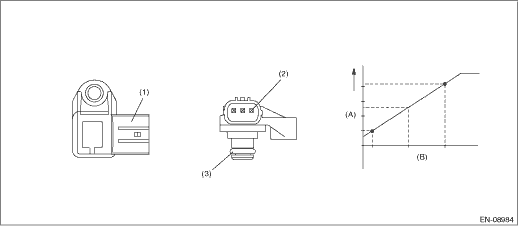
(A) | Output voltage | (B) | Absolute pressure | ||
(1) | Connector | (2) | Terminals | (3) | O-ring |
3. EXECUTION CONDITION
Secondary Parameters | Execution condition |
None |
4. GENERAL DRIVING CYCLE
Always perform the diagnosis continuously.
5. DIAGNOSTIC METHOD
If the duration of time while the following conditions are met is longer than the time indicated, judge as NG.
Malfunction Criteria | Threshold Value |
Output voltage | ≤ 0.608 V |
Time Needed for Diagnosis: 2000 ms
Malfunction Indicator Light Illumination: Illuminates as soon as a malfunction occurs.
 Dtc p0103 mass or volume air flow sensor "a" circuit high
ENGINE (DIAGNOSTICS)(H4DO) > Diagnostic Procedure with Diagnostic Trouble Code (DTC)DTC P0103 MASS OR VOLUME AIR FLOW SENSOR "A" CIRCUIT HIGHDTC detecting condition:Immediately at fault r ...
 Dtc p0108 manifold absolute pressure/barometric pressure sensor circuit high
ENGINE (DIAGNOSTICS)(H4DO) > Diagnostic Procedure with Diagnostic Trouble Code (DTC)DTC P0108 MANIFOLD ABSOLUTE PRESSURE/BAROMETRIC PRESSURE SENSOR CIRCUIT HIGHDTC detecting condition:Immediately a ...
Other materials:
Disassembly
DRIVE SHAFT SYSTEM > Rear Drive ShaftDISASSEMBLY1. Remove the outer race (DOJ) from the shaft assembly.CAUTION:Be careful not to damage the boot.(1) Using a flat tip screwdriver or pliers, loosen the boot band on the large end of boot (DOJ).CAUTION:Be careful not to damage the boot.(2) Remove the ...
Dtc c2541 vehicle dynamics control module vehicle speed sensor
POWER ASSISTED SYSTEM (POWER STEERING) (DIAGNOSTICS) > Diagnostic Procedure with Diagnostic Trouble Code (DTC)DTC C2541 VEHICLE DYNAMICS CONTROL MODULE VEHICLE SPEED SENSORTrouble symptom:The steering wheel operation feels heavy.STEPCHECKYESNO1.CHECK DTC.Read the DTC of the VDC system using the S ...
Dtc u1500 keyless uart com. Malfunction
BODY CONTROL SYSTEM (DIAGNOSTICS) > Diagnostic Procedure with Diagnostic Trouble Code (DTC)DTC U1500 KEYLESS UART COM. MALFUNCTION1. MODEL WITHOUT KEYLESS ACCESS WITH PUSH BUTTON START SYSTEMDTC detecting condition:UART between the TPMS & keyless control module or keyless entry CM and the bod ...
