Subaru Crosstrek Service Manual: Dtc p0108 manifold absolute pressure/barometric pressure sensor circuit high
ENGINE (DIAGNOSTICS)(H4DO) > Diagnostic Procedure with Diagnostic Trouble Code (DTC)
DTC P0108 MANIFOLD ABSOLUTE PRESSURE/BAROMETRIC PRESSURE SENSOR CIRCUIT HIGH
DTC detecting condition:
Immediately at fault recognition
CAUTION:
After servicing or replacing faulty parts, perform Clear Memory Mode Clear Memory Mode > OPERATION"> , and Inspection Mode Inspection Mode > PROCEDURE">.
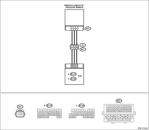
Wiring diagram:
Engine electrical system Engine Electrical System">
| STEP | CHECK | YES | NO |
1.CHECK CURRENT DATA.
1) Start the engine.
2) Read the value of «Mani. Absolute Pressure» using the Subaru Select Monitor or a general scan tool.
NOTE:
• Subaru Select Monitor
For detailed operation procedures, refer to “Current Data Display For Engine”. Subaru Select Monitor">
• General scan tool
For detailed operation procedures, refer to the general scan tool operation manual.
Is the value of «Mani. Absolute Pressure» 119.5 kPa (896.5 mmHg, 35.29 inHg) or more?
Diagnostic Procedure with Diagnostic Trouble Code (DTC) > DTC P0108 MANIFOLD ABSOLUTE PRESSURE/BAROMETRIC PRESSURE SENSOR CIRCUIT HIGH">Go to Step 2.
Even if DTC is detected, the circuit has returned to a normal condition at this time. Reproduce the failure, and then perform the diagnosis again.
NOTE:
In this case, temporary poor contact of connector, temporary open or short circuit of harness may be the cause.
2.CHECK HARNESS BETWEEN ECM AND MANIFOLD ABSOLUTE PRESSURE SENSOR CONNECTOR.
1) Turn the ignition switch to OFF.
2) Disconnect the connector from manifold absolute pressure sensor.
3) Start the engine.
4) Read the value data of «Mani. Absolute Pressure» using the Subaru Select Monitor or a general scan tool.
NOTE:
• Subaru Select Monitor
For detailed operation procedures, refer to “Current Data Display For Engine”. Subaru Select Monitor">
• General scan tool
For detailed operation procedures, refer to the general scan tool operation manual.
Is the value of «Mani. Absolute Pressure» 119.5 kPa (896.5 mmHg, 35.29 inHg) or more?
Repair the short circuit to power in harness between ECM connector and manifold absolute pressure sensor connector.
Diagnostic Procedure with Diagnostic Trouble Code (DTC) > DTC P0108 MANIFOLD ABSOLUTE PRESSURE/BAROMETRIC PRESSURE SENSOR CIRCUIT HIGH">Go to Step 3.
3.CHECK HARNESS BETWEEN ECM AND MANIFOLD ABSOLUTE PRESSURE SENSOR CONNECTOR.
1) Turn the ignition switch to OFF.
2) Measure the resistance of harness between manifold absolute pressure sensor connector and engine ground.
Connector & terminal
(E21) No. 1 — Engine ground:
Is the resistance less than 5 ??
Diagnostic Procedure with Diagnostic Trouble Code (DTC) > DTC P0108 MANIFOLD ABSOLUTE PRESSURE/BAROMETRIC PRESSURE SENSOR CIRCUIT HIGH">Go to Step 4.
Repair the harness and connector.
NOTE:
In this case, repair the following item:
• Open circuit of harness between ECM connector and manifold absolute pressure sensor connector
• Poor contact of ECM connector
• Poor contact of coupling connector
4.CHECK FOR POOR CONTACT.
Check for poor contact of manifold absolute pressure sensor connector.
Is there poor contact of manifold absolute pressure sensor connector?
Repair the poor contact of manifold absolute pressure sensor connector.
Replace the manifold absolute pressure sensor. Manifold Absolute Pressure Sensor">
1. OUTLINE OF DIAGNOSIS
Detect the open or short circuit of intake manifold pressure sensor.
Judge as NG if out of specification.
2. COMPONENT DESCRIPTION
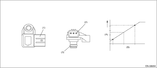
(A) | Output voltage | (B) | Absolute pressure | ||
(1) | Connector | (2) | Terminals | (3) | O-ring |
3. EXECUTION CONDITION
Secondary Parameters | Execution condition |
None |
4. GENERAL DRIVING CYCLE
Always perform the diagnosis continuously.
5. DIAGNOSTIC METHOD
If the duration of time while the following conditions are met is longer than the time indicated, judge as NG.
Malfunction Criteria | Threshold Value |
Output voltage | ≥ 3.906 V |
Time Needed for Diagnosis: 2000 ms
Malfunction Indicator Light Illumination: Illuminates as soon as a malfunction occurs.
 Dtc p0107 manifold absolute pressure/barometric pressure sensor circuit low
ENGINE (DIAGNOSTICS)(H4DO) > Diagnostic Procedure with Diagnostic Trouble Code (DTC)DTC P0107 MANIFOLD ABSOLUTE PRESSURE/BAROMETRIC PRESSURE SENSOR CIRCUIT LOWDTC detecting condition:Immediately at ...
 Dtc p0111 intake air temperature sensor 1 circuit range/performance bank 1
ENGINE (DIAGNOSTICS)(H4DO) > Diagnostic Procedure with Diagnostic Trouble Code (DTC)DTC P0111 INTAKE AIR TEMPERATURE SENSOR 1 CIRCUIT RANGE/PERFORMANCE BANK 1DTC detecting condition:Detected when t ...
Other materials:
Brake booster
If the brake booster does not operate as
described in the following, have it checked
by your SUBARU dealer.
1. With the ignition switch in the "LOCK"/
"OFF" position, depress the brake pedal
several times, applying the same pedal
force each time. The distance the pedal
travels should not va ...
Installation
CLUTCH SYSTEM > Clutch PedalINSTALLATION1. Install in the reverse order of removal.CAUTION:Always use a new clevis pin.Tightening torque:Clutch pedal18 N·m (1.8 kgf-m, 13.3 ft-lb)Knee airbag module7.5 N·m (0.76 kgf-m, 5.5 ft-lb)Air intake boot3 N·m (0.3 kgf-m, 2.2 ft-lb)2. Ad ...
Dtc p0752 shift solenoid "a" stuck on
CONTINUOUSLY VARIABLE TRANSMISSION (DIAGNOSTICS) > Diagnostic Procedure with Diagnostic Trouble Code (DTC)DTC P0752 SHIFT SOLENOID "A" STUCK ONDTC detecting condition:Detected when two consecutive driving cycles with fault occur.Trouble symptom:• Acceleration is poor during standi ...
