
Subaru Crosstrek Service Manual: Dtc c2514 torque sensor power supply
POWER ASSISTED SYSTEM (POWER STEERING) (DIAGNOSTICS) > Diagnostic Procedure with Diagnostic Trouble Code (DTC)
DTC C2514 TORQUE SENSOR POWER SUPPLY
Trouble symptom:
• The steering wheel operation feels heavy.
• STEERING warning light illuminates.
Wiring diagram:
Electric power steering system Electric Power Steering System">
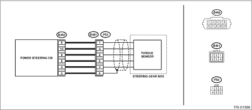
| STEP | CHECK | YES | NO |
1.CHECK TORQUE SENSOR SIGNAL.
1) Display the current data of the power steering control module using the Subaru Select Monitor.
2) Check the voltage of «Torque sensor main output», «Torque sensor sub output», «Torque sensor reference voltage» and «Torque sensor power supply voltage».
Are the voltage of «Torque sensor main output» and «Torque sensor sub output» 2.5±0.1 V?
Is the voltage of «Torque sensor reference voltage» 3±0.1 V?
Is the voltage of «Torque sensor power supply voltage» 8±0.4 V?
Check for poor contact of the connector, and check the conditions again. If the condition recur, go to the next step. Diagnostic Procedure with Diagnostic Trouble Code (DTC) > DTC C2514 TORQUE SENSOR POWER SUPPLY">Go to Step 2.
If it does not recur, complete the inspection.
Diagnostic Procedure with Diagnostic Trouble Code (DTC) > DTC C2514 TORQUE SENSOR POWER SUPPLY">Go to Step 2.
2.CHECK HARNESS.
1) Turn the ignition switch to OFF.
2) Disconnect the connector (B451).
3) Using a tester and test harness, check the internal resistance of the harness terminals.
Connector & terminal
(B450) No. 4 — (B451) No. 3:
(B450) No. 5 — (B451) No. 5:
(B450) No. 8 — (B451) No. 1:
(B450) No. 9 — (B451) No. 2:
(B450) No. 10 — (B451) No. 4:
Is the resistance less than 10 ??
Replace the power steering control module. Power Steering Control Module">
Repair or replace the harness.
 Dtc c2513 torque sensor much tolerance
POWER ASSISTED SYSTEM (POWER STEERING) (DIAGNOSTICS) > Diagnostic Procedure with Diagnostic Trouble Code (DTC)DTC C2513 TORQUE SENSOR MUCH TOLERANCENOTE:Refer to “DTC C2511 TORQUE SENSOR MAIN ...
 Dtc c2521 motor malfunction
POWER ASSISTED SYSTEM (POWER STEERING) (DIAGNOSTICS) > Diagnostic Procedure with Diagnostic Trouble Code (DTC)DTC C2521 MOTOR MALFUNCTIONTrouble symptom:• The steering wheel operation feels h ...
Other materials:
Dtc u0073 control module communication bus off
Blind Spot Detection/Rear Cross Traffic Alert (DIAGNOSTICS) > Diagnostic Procedure with Diagnostic Trouble Code (DTC)DTC U0073 CONTROL MODULE COMMUNICATION BUS OFFDetected when CAN line abnormality is detected.NOTE:Perform the diagnosis for LAN system. Basic Diagnostic Procedure > PROCEDURE&q ...
Dtc c1421 ecm control system
VEHICLE DYNAMICS CONTROL (VDC) (DIAGNOSTICS) > Diagnostic Procedure with Diagnostic Trouble Code (DTC)DTC C1421 ECM CONTROL SYSTEMDTC detecting condition:ECM malfunctioningTrouble symptom:• ABS does not operate.• VDC does not operate.• Hill start assist does not operate.STEPCHEC ...
Removal
FUEL INJECTION (FUEL SYSTEMS)(H4DO) > Camshaft Position SensorREMOVAL1. INTAKE SIDE1. Disconnect the ground cable from battery.2. Remove the air intake duct. (RH side only) Air Intake Duct > REMOVAL">3. Disconnect the connector (A) from the camshaft position sensor, and remove the cam ...
