Subaru Crosstrek Service Manual: Dtc c1362 normal closing valve 2
VEHICLE DYNAMICS CONTROL (VDC) (DIAGNOSTICS) > Diagnostic Procedure with Diagnostic Trouble Code (DTC)
DTC C1362 NORMAL CLOSING VALVE 2
DTC detecting condition:
• Defective harness connector
• Defective VDCH/U solenoid valve
Trouble symptom:
• ABS does not operate.
• EBD does not operate.
• VDC does not operate.
• Hill start assist does not operate.
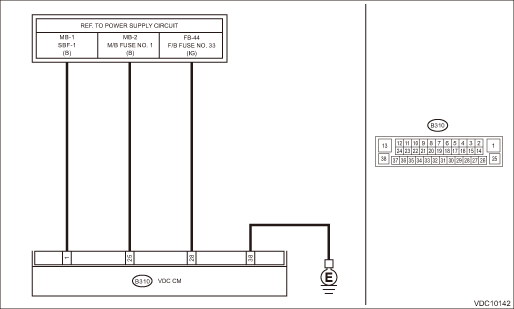
Wiring diagram:
Vehicle dynamics control system Vehicle Dynamics Control System > WIRING DIAGRAM">
| STEP | CHECK | YES | NO |
1.CHECK VDCCM&H/U INPUT VOLTAGE.
1) Turn the ignition switch to OFF.
2) Disconnect the connector from the VDCCM&H/U.
3) Run the engine at idle.
4) Measure the voltage between VDCCM&H/U connector and chassis ground.
Connector & terminal
(B310) No. 1 (+) — Chassis ground (−):
(B310) No. 25 (+) — Chassis ground (−):
(B310) No. 28 (+) — Chassis ground (−):
Is the voltage 10 — 15 V?
Diagnostic Procedure with Diagnostic Trouble Code (DTC) > DTC C1362 NORMAL CLOSING VALVE 2">Go to Step 2.
Repair the power supply circuit including the battery.
2.CHECK VDCCM&H/U GROUND CIRCUIT (CHECK FOR OPEN CIRCUIT).
1) Turn the ignition switch to OFF.
2) Measure the resistance between VDCCM&H/U connector and chassis ground.
Connector & terminal
(B310) No. 38 — Chassis ground:
Is the resistance less than 10 ??
Diagnostic Procedure with Diagnostic Trouble Code (DTC) > DTC C1362 NORMAL CLOSING VALVE 2">Go to Step 3.
Repair the VDCCM&H/U ground harness.
3.CHECK POOR CONTACT OF CONNECTORS.
Is there poor contact of connector between generator, battery and VDCCM&H/U?
Repair the connector.
Diagnostic Procedure with Diagnostic Trouble Code (DTC) > DTC C1362 NORMAL CLOSING VALVE 2">Go to Step 4.
4.CHECK VDCCM&H/U.
1) Connect all connectors.
2) Perform the Clear Memory Mode. Clear Memory Mode">
3) Perform the Inspection Mode. Inspection Mode">
4) Read the DTC. Read Diagnostic Trouble Code (DTC)">
Is the same DTC displayed?
Replace the VDCCM&H/U. VDC Control Module and Hydraulic Control Unit (VDCCM&H/U)">
Diagnostic Procedure with Diagnostic Trouble Code (DTC) > DTC C1362 NORMAL CLOSING VALVE 2">Go to Step 5.
5.CHECK DETECTION OF OTHER DTCS FOR VDC.
Read Diagnostic Trouble Code (DTC)">
Is any other DTC displayed?
Perform the diagnosis according to DTC. List of Diagnostic Trouble Code (DTC)">
Currently, it is normal. There may have been a temporary poor contact in the harness and connector or a temporary noise interference.
 Dtc c1361 normal closing valve 1
VEHICLE DYNAMICS CONTROL (VDC) (DIAGNOSTICS) > Diagnostic Procedure with Diagnostic Trouble Code (DTC)DTC C1361 NORMAL CLOSING VALVE 1NOTE:For the diagnostic procedure, refer to “DTC C1362 NO ...
 Dtc c1411 electrical control module
VEHICLE DYNAMICS CONTROL (VDC) (DIAGNOSTICS) > Diagnostic Procedure with Diagnostic Trouble Code (DTC)DTC C1411 ELECTRICAL CONTROL MODULEDTC detecting condition:Defective VDCCMTrouble symptom:&bull ...
Other materials:
Caution
MECHANICAL(H4DO) > General DescriptionCAUTION• Prior to starting work, pay special attention to the following:1. Always wear work clothes, a work cap, and protective shoes. Additionally, wear a helmet, protective goggles, etc. if necessary.2. Protect the vehicle using a seat cover, fender c ...
X-MODE
WARNING
When operating the Subaru Ascent with X-MODE engaged, always remain fully
attentive. Overestimating the system’s capabilities can lead to hazardous situations
and potentially serious accidents.
Use extreme caution when relying on the hill descent control function
in the Suba ...
Disposal of pretensioner Procedure
SEAT BELT SYSTEM > Disposal of PretensionerPROCEDUREWARNING:Make sure to follow the instructions below. Otherwise, personal injuries may occur.• Before discarding a pretensioner, always perform an activation process to prevent any false activation.• Wear protective gloves, safety gogg ...
