Subaru Crosstrek Service Manual: Dtc b27a2 passenger side external antenna open
KEYLESS ACCESS WITH PUSH BUTTON START SYSTEM (DIAGNOSTICS) > Diagnostic Procedure with Diagnostic Trouble Code (DTC)
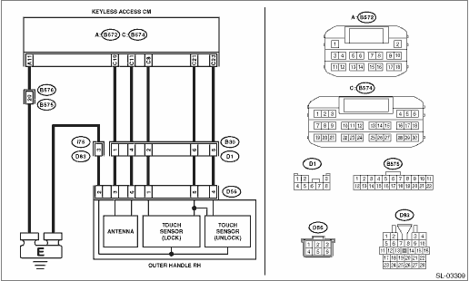
DTC B27A2 PASSENGER SIDE EXTERNAL ANTENNA OPEN
DTC detecting condition:
When open circuit occurs in the harness between keyless access CM and passenger’s side front door outer handle.
Trouble symptom:
Keyless access system does not function.
CAUTION:
For replacement procedure of keyless access CM, refer to the “REGISTRATION MANUAL FOR IMMOBILIZER” provided as a separate volume.
Wiring diagram:
Keyless access system Keyless Access System > WIRING DIAGRAM">
| STEP | CHECK | YES | NO |
1.CHECK LAN SYSTEM.
Inspect LAN system. Basic Diagnostic Procedure > PROCEDURE">
Is LAN system normal?
Diagnostic Procedure with Diagnostic Trouble Code (DTC) > DTC B27A2 PASSENGER SIDE EXTERNAL ANTENNA OPEN">Go to Step 2.
Perform the inspection according to the diagnosis for LAN system.
2.CHECK CONNECTOR.
1) Disconnect the keyless access CM connector.
2) Disconnect the front door outer handle connector.
Is the connector OK?
Diagnostic Procedure with Diagnostic Trouble Code (DTC) > DTC B27A2 PASSENGER SIDE EXTERNAL ANTENNA OPEN">Go to Step 3.
Repair or replace the connector.
3.CHECK HARNESS (OPEN CIRCUIT).
Using a tester, measure the resistance between the keyless access CM connector and front door outer handle connector, and between front door outer handle connector, keyless access CM connector and chassis ground.
Connector & terminal
(B574) No. 11 — (D56) No. 6:
(B574) No. 10 — (D56) No. 3:
(D56) No. 2 — Chassis ground:
(B572) No. 11 — Chassis ground:
Is the resistance less than 1 ??
Diagnostic Procedure with Diagnostic Trouble Code (DTC) > DTC B27A2 PASSENGER SIDE EXTERNAL ANTENNA OPEN">Go to Step 4.
Repair or replace the open circuit of harness.
4.CHECK HARNESS (GROUND SHORT CIRCUIT).
Using a tester, measure the resistance between the keyless access CM connector and chassis ground.
Connector & terminal
(B574) No. 11 — Chassis ground:
(B574) No. 10 — Chassis ground:
Is the resistance 10 k? or more?
Diagnostic Procedure with Diagnostic Trouble Code (DTC) > DTC B27A2 PASSENGER SIDE EXTERNAL ANTENNA OPEN">Go to Step 5.
Repair or replace the short circuit of the harness.
5.CHECK DTC.
1) Connect the keyless access CM connector.
2) Using the Subaru Select Monitor, clear the memory. Clear Memory Mode">
3) Read the DTC using Subaru Select Monitor. Read Diagnostic Trouble Code (DTC)">
Is DTC B27A2 displayed?
Diagnostic Procedure with Diagnostic Trouble Code (DTC) > DTC B27A2 PASSENGER SIDE EXTERNAL ANTENNA OPEN">Go to Step 6.
Even if DTC is displayed, the circuit has returned to a normal condition at this time. Reproduce the failure, and then perform the diagnosis again.
NOTE:
In this case, temporary poor contact of connector, temporary open or short circuit of harness may be the cause.
6.CHECK FRONT DOOR OUTER HANDLE.
1) Replace the passenger’s side front door outer handle with the driver’s front door outer handle. Front Outer Handle">
2) Using the Subaru Select Monitor, clear the memory. Clear Memory Mode">
3) Read the DTC using Subaru Select Monitor. Read Diagnostic Trouble Code (DTC)">
Is DTC B27A2 displayed?
Replace the keyless access CM. Keyless Access CM">
Replace the passenger’s side front door outer handle. Front Outer Handle">
 Dtc b27a1 driver side external antenna open
KEYLESS ACCESS WITH PUSH BUTTON START SYSTEM (DIAGNOSTICS) > Diagnostic Procedure with Diagnostic Trouble Code (DTC)DTC B27A1 DRIVER SIDE EXTERNAL ANTENNA OPENDTC detecting condition:When open circ ...
 Dtc b27a5 front internal antenna open
KEYLESS ACCESS WITH PUSH BUTTON START SYSTEM (DIAGNOSTICS) > Diagnostic Procedure with Diagnostic Trouble Code (DTC)DTC B27A5 FRONT INTERNAL ANTENNA OPENDTC detecting condition:When open circuit oc ...
Other materials:
Installation
STARTING/CHARGING SYSTEMS(H4DO) > StarterINSTALLATIONInstall in the reverse order of removal.NOTE:• For CVT model, a nut is used at (a).• Tighten the starter and cable stay (b) together using the upper bolt securing the starter.Tightening torque:T1: 14 N·m (1.4 kgf-m, 10.3 ft-l ...
Dtc p0201 cylinder 1 injector "a" circuit
ENGINE (DIAGNOSTICS)(H4DO) > Diagnostic Procedure with Diagnostic Trouble Code (DTC)DTC P0201 CYLINDER 1 INJECTOR "A" CIRCUITDTC DETECTING CONDITION:Immediately at fault recognitionTROUBLE SYMPTOM:• Improper idling• Poor driving performanceCAUTION:After servicing or replacin ...
Menu screens
Pull the "
/SET" switch to enter the menu
screens when all of the following conditions
are satisfied.
The vehicle has been completely
stopped.
The select lever is in the "P" position.
The menu screen entering screen is
selected.
The "
" information reminder is off.
Th ...
