Subaru Crosstrek Service Manual: Dtc b2786 steering lock cm communication
KEYLESS ACCESS WITH PUSH BUTTON START SYSTEM (DIAGNOSTICS) > Diagnostic Procedure with Diagnostic Trouble Code (DTC)
DTC B2786 STEERING LOCK CM COMMUNICATION
DTC detecting condition:
When communication between keyless access CM and steering lock CM is interrupted for a set amount of time.
Trouble symptom:
The steering lock cannot be released.
CAUTION:
For replacement procedure of keyless access CM and steering lock CM, refer to the “REGISTRATION MANUAL FOR IMMOBILIZER” provided as a separate volume.
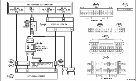
Wiring diagram:
Push button start system Push Button Start System > WIRING DIAGRAM">
| STEP | CHECK | YES | NO |
1.CHECK DTC.
Read the DTC using the Subaru Select Monitor. Read Diagnostic Trouble Code (DTC)">
Is a DTC other than DTC B2786 displayed?
Perform the diagnosis according to DTC.
Diagnostic Procedure with Diagnostic Trouble Code (DTC) > DTC B2786 STEERING LOCK CM COMMUNICATION">Go to Step 2.
2.CHECK HARNESS (OPEN CIRCUIT).
1) Disconnect the keyless access CM connector.
2) Disconnect the steering lock CM connector.
3) Using the tester, measure the resistance between terminals.
Connector & terminal
(B574) No. 17 — (B424) No. 5:
Is the resistance less than 1 ??
Diagnostic Procedure with Diagnostic Trouble Code (DTC) > DTC B2786 STEERING LOCK CM COMMUNICATION">Go to Step 3.
Repair or replace the open circuit of harness.
3.CHECK HARNESS (GROUND SHORT CIRCUIT).
Using the tester, measure the resistance between terminals.
Connector & terminal
(B574) No. 17 — Chassis ground:
Is the resistance 10 k? or more?
Diagnostic Procedure with Diagnostic Trouble Code (DTC) > DTC B2786 STEERING LOCK CM COMMUNICATION">Go to Step 4.
Repair or replace the short circuit of the harness.
4.CHECK HARNESS (OPEN CIRCUIT).
Using a tester, measure the resistance between the steering lock CM connector and chassis ground.
Connector & terminal
(B424) No. 1 — Chassis ground:
Is the resistance less than 1 ??
Diagnostic Procedure with Diagnostic Trouble Code (DTC) > DTC B2786 STEERING LOCK CM COMMUNICATION">Go to Step 5.
Repair or replace the open circuit of harness.
5.CHECK HARNESS.
1) Turn the ignition switch to ON.
2) Using a tester, measure the voltage between the steering lock CM connector and chassis ground.
Connector & terminal
(B424) No. 6 (+) — Chassis ground (−):
(B424) No. 7 (+) — Chassis ground (−):
Is the voltage 11 — 14 V?
Diagnostic Procedure with Diagnostic Trouble Code (DTC) > DTC B2786 STEERING LOCK CM COMMUNICATION">Go to Step 6.
Repair or replace the faulty portion of the power supply circuit.
6.CHECK STEERING LOCK CM.
1) Turn the ignition switch to ON.
2) Using the Subaru Select Monitor, clear the memory. Clear Memory Mode">
3) Read the DTC using the Subaru Select Monitor. Read Diagnostic Trouble Code (DTC)">
Is DTC B2785 displayed?
Replace the keyless access CM. Keyless Access CM">
Diagnostic Procedure with Diagnostic Trouble Code (DTC) > DTC B2786 STEERING LOCK CM COMMUNICATION">Go to Step 7.
7.CHECK STEERING LOCK CM.
1) Turn the ignition switch to ON.
2) Using the Subaru Select Monitor, clear the memory. Clear Memory Mode">
3) Read the DTC using the Subaru Select Monitor. Read Diagnostic Trouble Code (DTC)">
Is DTC B2786 displayed?
Replace the steering lock CM. Steering Lock CM">
Even if DTC is displayed, the circuit has returned to a normal condition at this time. Reproduce the failure, and then perform the diagnosis again.
NOTE:
In this case, temporary poor contact of connector, temporary open or short circuit of harness may be the cause.
 Dtc b2785 lin communication
KEYLESS ACCESS WITH PUSH BUTTON START SYSTEM (DIAGNOSTICS) > Diagnostic Procedure with Diagnostic Trouble Code (DTC)DTC B2785 LIN COMMUNICATIONDTC detecting condition:When the keyless access CM det ...
 Dtc b2788 ign signal correlation (steering lock cm)
KEYLESS ACCESS WITH PUSH BUTTON START SYSTEM (DIAGNOSTICS) > Diagnostic Procedure with Diagnostic Trouble Code (DTC)DTC B2788 IGN SIGNAL CORRELATION (STEERING LOCK CM)DTC detecting condition:When m ...
Other materials:
Caution
VEHICLE DYNAMICS CONTROL (VDC) (DIAGNOSTICS) > General DescriptionCAUTION1. SUPPLEMENTAL RESTRAINT SYSTEM “AIRBAG”Airbag system wiring harness is routed near the ABS wheel speed sensor and VDCCM&H/U.CAUTION:• Do not use electrical test equipment on wiring harness and connect ...
Power rear gate
WARNING
When operating the Subaru Ascent power rear gate, always ensure the surrounding
area is clear of people and obstacles.
Failure to follow these precautions may result in injury due to impact
or entrapment.
Confirm that no one is standing near the Subaru Ascent rear gate.
...
Warning chimes and warning indicator of he keyless access with push-button start
system
Access key warning indicator
In the Subaru Ascent, the keyless access with push-button start system is designed
to enhance both convenience and security. The system emits warning chimes and activates
the access key warning indicator on the combination meter to alert the driver of
incorrec ...
