Subaru Crosstrek Service Manual: Dtc b19f3 short in front p/t 2 rh (to +b)
AIRBAG SYSTEM (DIAGNOSTICS) > Diagnostic Chart with Trouble Code
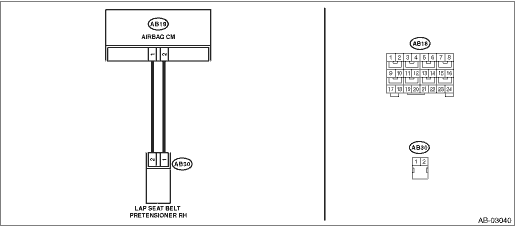
DTC B19F3 SHORT IN FRONT P/T 2 RH (TO +B)
Diagnosis start condition:
Ignition voltage is 10 V to 16 V.
DTC detecting condition:
• Lap seat belt pretensioner (RH) circuit is shorted to power supply.
• Lap seat belt pretensioner (RH) is faulty.
• Lap seat belt pretensioner harness (RH) is shorted to power supply.
• Airbag control module is faulty.
CAUTION:
Before performing diagnosis, refer to “CAUTION” in “General Description”. General Description > CAUTION">
Wiring diagram:
Airbag system Airbag System > WIRING DIAGRAM">
| STEP | CHECK | YES | NO |
1.CHECK POOR CONTACT OF CONNECTORS.
Check for poor contact of the connectors between the airbag control module and the lap seat belt pretensioner (RH).
Is there poor contact?
Replace the airbag rear harness along with body harness.
Diagnostic Chart with Trouble Code > DTC B19F3 SHORT IN FRONT P/T 2 RH (TO +B)">Go to Step 2.
2.CHECK LAP SEAT BELT PRETENSIONER.
1) Turn the ignition switch to OFF, disconnect the battery ground cable, and wait for 60 seconds or more.
2) Disconnect the connector (AB30) from lap seat belt pretensioner (RH).
3) Connect the connector (1N) in the test harness N to the connector (AB30).
4) Connect the airbag resistor to the connector (2N) of test harness N.
5) Connect the battery ground terminal and turn the ignition switch to ON.
Does the airbag warning light illuminate for 6 seconds and go off?
Replace the lap seat belt pretensioner (RH). Front Seat Belt > REMOVAL">
Diagnostic Chart with Trouble Code > DTC B19F3 SHORT IN FRONT P/T 2 RH (TO +B)">Go to Step 3.
3.CHECK AIRBAG REAR HARNESS (LAP SEAT BELT PRETENSIONER HARNESS RH).
1) Turn the ignition switch to OFF, disconnect the battery ground cable, and wait for 60 seconds or more.
2) Disconnect the airbag resistor from test harness N.
3) Disconnect the connector (AB33) from curtain airbag module (RH).
4) Disconnect connector (AB24) from side airbag module (RH).
5) Disconnect the connector (AB26) from seat belt pretensioner.
6) Disconnect the connectors (AB6, AB17, AB18) from airbag control module.
7) Connect the connector (1AG) in the test harness AG to the connectors (AB6, AB17, AB18).
8) Connect the battery ground terminal and turn the ignition switch to ON.
9) Measure the voltage between connector (3AG) in the test harness AG and chassis ground.
Connector & terminal
(3AG) No. 17 (+) — Chassis ground (−):
(3AG) No. 19 (+) — Chassis ground (−):
Is the voltage less than 1 V?
Diagnostic Chart with Trouble Code > DTC B19F3 SHORT IN FRONT P/T 2 RH (TO +B)">Go to Step 4.
Replace the airbag rear harness along with body harness.
4.CHECK AIRBAG CONTROL MODULE.
1) Connect all connectors.
2) Clear the memory. Clear Memory Mode">
3) Perform the Inspection Mode. Inspection Mode">
4) Read the DTC. (Current malfunction) Read Diagnostic Trouble Code (DTC)">
Is DTC B19F3 displayed?
Replace the airbag control module. Airbag Control Module">
Diagnostic Chart with Trouble Code > DTC B19F3 SHORT IN FRONT P/T 2 RH (TO +B)">Go to Step 5.
5.CHECK FOR ANY OTHER DTC ON DISPLAY.
Is any other DTC displayed?
Check DTC using “List of Diagnostic Trouble Code (DTC)”. List of Diagnostic Trouble Code (DTC)">
Finish the diagnosis.
 Dtc b19f2 short in front p/t 2 rh (to ground)
AIRBAG SYSTEM (DIAGNOSTICS) > Diagnostic Chart with Trouble CodeDTC B19F2 SHORT IN FRONT P/T 2 RH (TO GROUND)Diagnosis start condition:Ignition voltage is 10 V to 16 V.DTC detecting condition:&bull ...
 Dtc b19f1 open in front p/t 2 rh
AIRBAG SYSTEM (DIAGNOSTICS) > Diagnostic Chart with Trouble CodeDTC B19F1 OPEN IN FRONT P/T 2 RHDiagnosis start condition:Ignition voltage is 10 V to 16 V.DTC detecting condition:• Lap seat b ...
Other materials:
Operation
POWER ASSISTED SYSTEM (POWER STEERING) (DIAGNOSTICS) > Subaru Select MonitorOPERATION1. HOW TO USE SUBARU SELECT MONITORFor detailed operation procedures, refer to “Application help”.2. READ CURRENT DATA1. On «Start» display, select «Diagnosis».2. On «Vehicle selection» display, ...
Dtc c2424 transmitter 4 battery voltage low
TIRE PRESSURE MONITORING SYSTEM (DIAGNOSTICS) > Diagnostic Procedure with Diagnostic Trouble Code (DTC)DTC C2424 TRANSMITTER 4 BATTERY VOLTAGE LOWDTC DETECTING CONDITION:Detected when power supply voltage failure signal is received from each transmitter.TROUBLE SYMPTOM:Tire pressure warning light ...
Inspection
MANUAL TRANSMISSION AND DIFFERENTIAL(5MT) > Transmission Mounting SystemINSPECTIONCheck the following; repair or replace the faulty parts.1. PITCHING STOPPERCheck the pitching stopper for bends or damage. Check that the rubber is not stiff, cracked or otherwise damaged.2. CROSSMEMBER AND CUSHION ...
