
Subaru Crosstrek Service Manual: Dtc b19f1 open in front p/t 2 rh
AIRBAG SYSTEM (DIAGNOSTICS) > Diagnostic Chart with Trouble Code
DTC B19F1 OPEN IN FRONT P/T 2 RH
Diagnosis start condition:
Ignition voltage is 10 V to 16 V.
DTC detecting condition:
• Lap seat belt pretensioner (RH) circuit is open.
• Lap seat belt pretensioner (RH) is faulty.
• Lap seat belt pretensioner harness (RH) is open.
• Airbag control module is faulty.
CAUTION:
Before performing diagnosis, refer to “CAUTION” in “General Description”. General Description > CAUTION">
Wiring diagram:
Airbag system Airbag System > WIRING DIAGRAM">
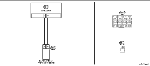
| STEP | CHECK | YES | NO |
1.CHECK POOR CONTACT OF CONNECTORS.
Check for poor contact of the connectors between the airbag control module and the lap seat belt pretensioner (RH).
Is there poor contact?
Replace the airbag rear harness along with body harness.
Diagnostic Chart with Trouble Code > DTC B19F1 OPEN IN FRONT P/T 2 RH">Go to Step 2.
2.CHECK LAP SEAT BELT PRETENSIONER.
1) Turn the ignition switch to OFF, disconnect the battery ground cable, and wait for 60 seconds or more.
2) Disconnect the connector (AB30) from lap seat belt pretensioner (RH).
3) Connect the connector (1N) in the test harness N to the connector (AB30).
4) Connect the airbag resistor to the connector (2N) of test harness N.
5) Connect the battery ground terminal and turn the ignition switch to ON.
Does the airbag warning light illuminate for 6 seconds and go off?
Replace the lap seat belt pretensioner (RH). Front Seat Belt > REMOVAL">
Diagnostic Chart with Trouble Code > DTC B19F1 OPEN IN FRONT P/T 2 RH">Go to Step 3.
3.CHECK AIRBAG REAR HARNESS (SIDE AIRBAG HARNESS RH).
1) Turn the ignition switch to OFF, disconnect the battery ground cable, and wait for 60 seconds or more.
2) Disconnect the airbag resistor from test harness N.
3) Disconnect the connector (AB33) from curtain airbag module (RH).
4) Disconnect connector (AB24) from side airbag module (RH).
5) Disconnect the connector (AB26) from seat belt pretensioner.
6) Disconnect the connectors (AB6, AB17, AB18) from airbag control module.
7) Connect the connector (1AG) in the test harness AG to the connectors (AB6, AB17, AB18).
8) Measure the resistance between connector (3AG) in the test harness AG and connector (2N) in the test harness N.
Connector & terminal
(3AG) No. 17 — (2N) No. 2:
(3AG) No. 19 — (2N) No. 1:
Is the resistance less than 10 ??
Diagnostic Chart with Trouble Code > DTC B19F1 OPEN IN FRONT P/T 2 RH">Go to Step 4.
Replace the airbag rear harness along with body harness.
4.CHECK AIRBAG CONTROL MODULE.
1) Connect all connectors.
2) Clear the memory. Clear Memory Mode">
3) Perform the Inspection Mode. Inspection Mode">
4) Read the DTC. (Current malfunction) Read Diagnostic Trouble Code (DTC)">
Is DTC B19F1 displayed?
Replace the airbag control module. Airbag Control Module">
Diagnostic Chart with Trouble Code > DTC B19F1 OPEN IN FRONT P/T 2 RH">Go to Step 5.
5.CHECK FOR ANY OTHER DTC ON DISPLAY.
Is any other DTC displayed?
Check DTC using “List of Diagnostic Trouble Code (DTC)”. List of Diagnostic Trouble Code (DTC)">
Finish the diagnosis.
 Dtc b19f3 short in front p/t 2 rh (to +b)
AIRBAG SYSTEM (DIAGNOSTICS) > Diagnostic Chart with Trouble CodeDTC B19F3 SHORT IN FRONT P/T 2 RH (TO +B)Diagnosis start condition:Ignition voltage is 10 V to 16 V.DTC detecting condition:• L ...
 Dtc b19f0 short in front p/t 2 rh
AIRBAG SYSTEM (DIAGNOSTICS) > Diagnostic Chart with Trouble CodeDTC B19F0 SHORT IN FRONT P/T 2 RHDiagnosis start condition:Ignition voltage is 10 V to 16 V.DTC detecting condition:• Lap seat ...
Other materials:
Dtc p2271 o2 sensor signal biased/stuck rich bank 1 sensor 2
ENGINE (DIAGNOSTICS)(H4DO) > Diagnostic Procedure with Diagnostic Trouble Code (DTC)DTC P2271 O2 SENSOR SIGNAL BIASED/STUCK RICH BANK 1 SENSOR 2DTC detecting condition:Detected when two consecutive driving cycles with fault occur.CAUTION:After servicing or replacing faulty parts, perform Clear Me ...
Installation
CONTINUOUSLY VARIABLE TRANSMISSION(TR580) > Transmission HarnessINSTALLATION1. INHIBITOR HARNESSInstall in the reverse order of removal.NOTE:Install the transmission ground terminal in the direction within the range of approx. 30° (A).Tightening torque:T1: 7 N·m (0.7 kgf-m, 3.7 ...
Dtc c2322 transmitter 2 function code abnormal
TIRE PRESSURE MONITORING SYSTEM (DIAGNOSTICS) > Diagnostic Procedure with Diagnostic Trouble Code (DTC)DTC C2322 TRANSMITTER 2 FUNCTION CODE ABNORMALNOTE:Refer to DTC C2324 for diagnostic procedure. Diagnostic Procedure with Diagnostic Trouble Code (DTC) > DTC C2324 TRANSMITTER 4 FUNCTION COD ...
