Subaru Crosstrek Service Manual: Dtc b1902 short in front p/t rh (to ground)
AIRBAG SYSTEM (DIAGNOSTICS) > Diagnostic Chart with Trouble Code
DTC B1902 SHORT IN FRONT P/T RH (TO GROUND)
Diagnosis start condition:
Ignition voltage is 10 V to 16 V.
DTC detecting condition:
• Seat belt pretensioner (RH) circuit is shorted to ground.
• Pretensioner (RH) is faulty.
• Pretensioner harness (RH) is faulty.
• Airbag control module is faulty.
CAUTION:
Before performing diagnosis, refer to “CAUTION” in “General Description”. General Description > CAUTION">
Wiring diagram:
Airbag system Airbag System > WIRING DIAGRAM">
| STEP | CHECK | YES | NO |
1.CHECK POOR CONTACT OF CONNECTORS.
Check for poor contact of the connectors between the airbag control module and the seat belt pretensioner RH.
Is there poor contact?
Replace the airbag rear harness along with body harness.
Diagnostic Chart with Trouble Code > DTC B1902 SHORT IN FRONT P/T RH (TO GROUND)">Go to Step 2.
2.CHECK SEAT BELT PRETENSIONER.
1) Turn the ignition switch to OFF, disconnect the battery ground cable, and wait for 60 seconds or more.
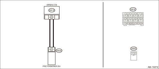
2) Disconnect the connector (AB26) from seat belt pretensioner (RH).
3) Connect the connector (1N) in the test harness N to the connector (AB26).
4) Connect the airbag resistor to the connector (2N) of test harness N.
5) Connect the battery ground terminal and turn the ignition switch to ON.
Does the airbag warning light illuminate for six seconds and go off?
Replace the seat belt pretensioner (RH). Front Seat Belt">
Diagnostic Chart with Trouble Code > DTC B1902 SHORT IN FRONT P/T RH (TO GROUND)">Go to Step 3.
3.CHECK AIRBAG REAR HARNESS (PRETENSIONER HARNESS RH).
1) Turn the ignition switch to OFF, disconnect the battery ground cable, and wait for 60 seconds or more.
2) Disconnect the airbag resistor from the connector (2N) of test harness N.
3) Disconnect connector (AB24) from side airbag module (RH).
4) Disconnect the connector (AB33) from curtain airbag module (RH).
5) Disconnect the connectors (AB6, AB17, AB18) from airbag control module.
6) Connect the connector (1AG) in the test harness AG to the connectors (AB6, AB17, AB18).
7) Measure the resistance between connector (3AG) in the test harness AG and chassis ground.
Connector & terminal
(3AG) No. 18 — Chassis ground:
(3AG) No. 20 — Chassis ground:
Is the resistance 1 M? or more?
Diagnostic Chart with Trouble Code > DTC B1902 SHORT IN FRONT P/T RH (TO GROUND)">Go to Step 4.
Replace the airbag rear harness along with body harness.
4.CHECK AIRBAG CONTROL MODULE.
1) Connect all connectors.
2) Clear the memory. Clear Memory Mode">
3) Perform the Inspection Mode. Inspection Mode">
4) Read the DTC. (Current malfunction) Read Diagnostic Trouble Code (DTC)">
Is DTC B1902 displayed?
Replace the airbag control module. Airbag Control Module">
Diagnostic Chart with Trouble Code > DTC B1902 SHORT IN FRONT P/T RH (TO GROUND)">Go to Step 5.
5.CHECK FOR ANY OTHER DTC ON DISPLAY.
Is any other DTC displayed?
Check DTC using “List of Diagnostic Trouble Code (DTC)”. List of Diagnostic Trouble Code (DTC)">
Finish the diagnosis.
 Dtc b1901 open in front p/t rh
AIRBAG SYSTEM (DIAGNOSTICS) > Diagnostic Chart with Trouble CodeDTC B1901 OPEN IN FRONT P/T RHDiagnosis start condition:Ignition voltage is 10 V to 16 V.DTC detecting condition:• Seat belt pr ...
 Dtc b1903 short in front p/t rh (to +b)
AIRBAG SYSTEM (DIAGNOSTICS) > Diagnostic Chart with Trouble CodeDTC B1903 SHORT IN FRONT P/T RH (TO +B)Diagnosis start condition:Ignition voltage is 10 V to 16 V.DTC detecting condition:• Sea ...
Other materials:
Maintenance precautions
When maintenance and service are required,
it is recommended that all work be
done by an authorized SUBARU dealer.
If you perform maintenance and service
by yourself, you should familiarize yourself
with the information provided in this
section on general maintenance and
service for your SU ...
General diagnostic table Inspection
POWER ASSISTED SYSTEM (POWER STEERING) > General Diagnostic TableINSPECTIONTroublePossible causeCorrective action• Steering effort is heavy in all ranges.• Steering effort is heavy at stand still.• Steering wheel vibrates when turning.1. Tire and wheel• Improper tire out o ...
Installation
REAR SUSPENSION > Rear Sub FrameINSTALLATIONCAUTION:• Be sure to use a new self-locking nut.• Always tighten the bushing in the state where the vehicle is at curb weight and the wheels are in full contact with the ground.• Install so that the front end of the under cover (b) com ...
