Subaru Crosstrek Service Manual: Dtc b1903 short in front p/t rh (to +b)
AIRBAG SYSTEM (DIAGNOSTICS) > Diagnostic Chart with Trouble Code
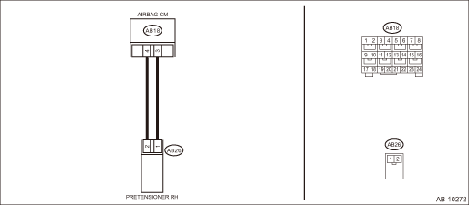
DTC B1903 SHORT IN FRONT P/T RH (TO +B)
Diagnosis start condition:
Ignition voltage is 10 V to 16 V.
DTC detecting condition:
• Seat belt pretensioner (RH) circuit is shorted to power supply.
• Pretensioner (RH) is faulty.
• Pretensioner harness (RH) is faulty.
• Airbag control module is faulty.
CAUTION:
Before performing diagnosis, refer to “CAUTION” in “General Description”. General Description > CAUTION">
Wiring diagram:
Airbag system Airbag System > WIRING DIAGRAM">
| STEP | CHECK | YES | NO |
1.CHECK POOR CONTACT OF CONNECTORS.
Check for poor contact of the connectors between the airbag control module and the seat belt pretensioner RH.
Is there poor contact?
Replace the airbag rear harness along with body harness.
Diagnostic Chart with Trouble Code > DTC B1903 SHORT IN FRONT P/T RH (TO +B)">Go to Step 2.
2.CHECK SEAT BELT PRETENSIONER.
1) Turn the ignition switch to OFF, disconnect the battery ground cable, and wait for 60 seconds or more.
2) Disconnect the connector (AB26) from seat belt pretensioner (RH).
3) Connect the connector (1N) in the test harness N to the connector (AB26).
4) Connect the airbag resistor to the connector (2N) of test harness N.
5) Connect the battery ground terminal and turn the ignition switch to ON.
Does the airbag warning light illuminate for six seconds and go off?
Replace the seat belt pretensioner (RH). Front Seat Belt">
Diagnostic Chart with Trouble Code > DTC B1903 SHORT IN FRONT P/T RH (TO +B)">Go to Step 3.
3.CHECK AIRBAG REAR HARNESS (PRETENSIONER HARNESS RH).
1) Turn the ignition switch to OFF, disconnect the battery ground cable, and wait for 60 seconds or more.
2) Disconnect the airbag resistor from the connector (2N) of test harness N.
3) Disconnect connector (AB24) from side airbag module (RH).
4) Disconnect the connector (AB33) from curtain airbag module (RH).
5) Disconnect the connectors (AB6, AB17, AB18) from airbag control module.
6) Connect the connector (1AG) in the test harness AG to the connectors (AB6, AB17, AB18).
7) Connect the battery ground terminal and turn the ignition switch to ON.
8) Measure the voltage between connector (3AG) in the test harness AG and chassis ground.
Connector & terminal
(3AG) No. 20 (+) — Chassis ground (−):
(3AG) No. 18 (+) — Chassis ground (−):
Is the voltage less than 1 V?
Diagnostic Chart with Trouble Code > DTC B1903 SHORT IN FRONT P/T RH (TO +B)">Go to Step 4.
Replace the airbag rear harness along with body harness.
4.CHECK AIRBAG CONTROL MODULE.
1) Connect all connectors.
2) Clear the memory. Clear Memory Mode">
3) Perform the Inspection Mode. Inspection Mode">
4) Read the DTC. (Current malfunction) Read Diagnostic Trouble Code (DTC)">
Is DTC B1903 displayed?
Replace the airbag control module. Airbag Control Module">
Diagnostic Chart with Trouble Code > DTC B1903 SHORT IN FRONT P/T RH (TO +B)">Go to Step 5.
5.CHECK FOR ANY OTHER DTC ON DISPLAY.
Is any other DTC displayed?
Check DTC using “List of Diagnostic Trouble Code (DTC)”. List of Diagnostic Trouble Code (DTC)">
Finish the diagnosis.
 Dtc b1902 short in front p/t rh (to ground)
AIRBAG SYSTEM (DIAGNOSTICS) > Diagnostic Chart with Trouble CodeDTC B1902 SHORT IN FRONT P/T RH (TO GROUND)Diagnosis start condition:Ignition voltage is 10 V to 16 V.DTC detecting condition:• ...
 Dtc b16f0 passenger s airbag off indicator failure
AIRBAG SYSTEM (DIAGNOSTICS) > Diagnostic Chart with Trouble CodeDTC B16F0 PASSENGER’S AIRBAG OFF INDICATOR FAILURENOTE:For details on DTC B16F0, refer to DTC B1660. Diagnostic Chart with Tro ...
Other materials:
Rear window wiper blade assembly
1. Raise the wiper arm off the rear
window.
2. Turn the wiper blade assembly counterclockwise.
3. Pull the wiper blade assembly toward
you to remove it from the wiper arm.
4. Install the wiper blade assembly to the
wiper arm. Make sure that it locks in place.
5. Hold the wiper arm ...
Installation
BRAKE > Front Disc Brake AssemblyINSTALLATIONNOTE:Before installation, remove mud and foreign matter from the caliper body assembly and support - front disc brake.1. Check each part. Front Disc Brake Assembly > INSPECTION">2. Apply a thin coat of grease to the support - front disc bra ...
Installation
MECHANICAL(H4DO) > Engine AssemblyINSTALLATION1. Install the engine mounting onto the engine.Tightening torque:35 N·m (3.6 kgf-m, 25.8 ft-lb)2. Apply a small amount of grease to splines of main shaft. (MT model)Grease:NICHIMOLY N-130 or equivalent3. Position the engine in engine compartmen ...
