Subaru Crosstrek Service Manual: Dtc b14e6 mode door actuator stepping motor circuit short-circuit
HVAC SYSTEM (AUTO A/C) (DIAGNOSTICS) > Diagnostic Procedure with Diagnostic Trouble Code (DTC)
DTC B14E6 MODE DOOR ACTUATOR STEPPING MOTOR CIRCUIT SHORT-CIRCUIT
DTC detecting condition:
Mode door actuator stepping motor circuit is shorted.
Trouble symptom:
Vent does not change.
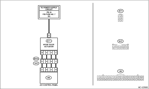
Wiring diagram:
Air conditioning system Air Conditioning System > WIRING DIAGRAM">
| STEP | CHECK | YES | NO |
1.CHECK CONNECTOR.
1) Check the condition of connector connection.
2) Read the DTC using Subaru Select Monitor. Read Diagnostic Trouble Code (DTC)">
Is B14E6 displayed?
Diagnostic Procedure with Diagnostic Trouble Code (DTC) > DTC B14E6 MODE DOOR ACTUATOR STEPPING MOTOR CIRCUIT SHORT-CIRCUIT">Go to Step 2.
Even if DTC is displayed, the circuit has returned to a normal condition at this time. Reproduce the failure, and then perform the diagnosis again.
NOTE:
In this case, temporary poor contact of connector, temporary open or short circuit of harness may be the cause.
2.CHECK POWER SUPPLY FOR MODE DOOR ACTUATOR.
1) Turn the ignition switch to OFF.
2) Disconnect the mode door actuator connector.
3) Turn the ignition switch to ON.
4) Measure the voltage between the mode door actuator connector terminal and chassis ground.
Connector & terminal
(B77) No. 3 (+) — Chassis ground (–):
Is the voltage approx. 10 V or more?
Diagnostic Procedure with Diagnostic Trouble Code (DTC) > DTC B14E6 MODE DOOR ACTUATOR STEPPING MOTOR CIRCUIT SHORT-CIRCUIT">Go to Step 3.
Check the DC power supply circuit.
3.CHECK MODE DOOR ACTUATOR.
1) Turn the ignition switch to OFF.
2) Measure the resistance between mode door actuator terminals using a tester.
Connector & terminal
(B77) No. 3 — No. 1:
(B77) No. 3 — No. 2:
(B77) No. 3 — No. 5:
(B77) No. 3 — No. 6:
Is the resistance 80 — 100 ??
Diagnostic Procedure with Diagnostic Trouble Code (DTC) > DTC B14E6 MODE DOOR ACTUATOR STEPPING MOTOR CIRCUIT SHORT-CIRCUIT">Go to Step 4.
Replace the actuator. Mode Door Actuator > REMOVAL">
4.CHECK HARNESS BETWEEN A/C CONTROL PANEL AND MODE DOOR ACTUATOR (SHORTED TO POWER SUPPLY).
1) Disconnect the A/C control panel connector.
2) Turn the ignition switch to ON.
3) Measure the voltage between mode door actuator connector and chassis ground.
Connector & terminal
(B77) No. 1 (+) — Chassis ground (−):
(B77) No. 2 (+) — Chassis ground (−):
(B77) No. 5 (+) — Chassis ground (−):
(B77) No. 6 (+) — Chassis ground (−):
Is there any voltage?
Repair or replace the short circuit of the harness.
Replace the A/C control panel. Control Panel > REMOVAL">
 Dtc b14e5 mode door actuator stepping motor circuit open
HVAC SYSTEM (AUTO A/C) (DIAGNOSTICS) > Diagnostic Procedure with Diagnostic Trouble Code (DTC)DTC B14E5 MODE DOOR ACTUATOR STEPPING MOTOR CIRCUIT OPENDTC detecting condition:Mode door actuator step ...
 Dtc b14e9 intake door actuator circuit open
HVAC SYSTEM (AUTO A/C) (DIAGNOSTICS) > Diagnostic Procedure with Diagnostic Trouble Code (DTC)DTC B14E9 INTAKE DOOR ACTUATOR CIRCUIT OPENDTC detecting condition:Intake door actuator potentiometer c ...
Other materials:
SRS airbag system servicing
WARNING
When disposing of an airbag module or scrapping a Subaru Ascent that
has been involved in a collision, always consult an authorized SUBARU dealer
to ensure safe handling and disposal.
The Subaru Ascent SRS airbag system contains no user-serviceable components.
Never attempt to ...
Before using aha application
In order to use the aha application on this
system, the application must be installed
on the smartphone.
Settings required to use aha
application
Search and download the aha application
from your smartphone app store.
iPhone and iPod touch: Apple App
Store via iTunes
Android device ...
Inspection
LIGHTING SYSTEM > Door SwitchINSPECTION1. Check the resistance between switch terminals.Preparation tool:Circuit testerTerminal No.Inspection conditionsStandardConnection diagram1 — 3When door is openedLess than 1 ?When door is closed1 M? or more2. Replace the switch assembly - door if the insp ...
