Subaru Crosstrek Service Manual: Dtc b1016 shift lock circuit
BODY CONTROL SYSTEM (DIAGNOSTICS) > Diagnostic Procedure with Diagnostic Trouble Code (DTC)
DTC B1016 SHIFT LOCK CIRCUIT
DTC detecting condition:
Open or power supply-output short, GND-output short in shift lock circuit.
Trouble symptom:
Shift lock does not be released or remain locked.
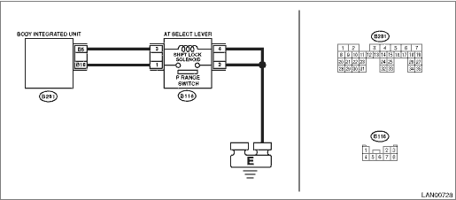
Wiring diagram:
Shift lock control system Shift Lock Control System > WIRING DIAGRAM">

| STEP | CHECK | YES | NO |
1.CHECK DTC.
1) Turn the ignition switch to ON.
2) Keep the Parking range for approx. 5 seconds.
3) Read the DTC of body integrated unit using Subaru Select Monitor. Read Diagnostic Trouble Code (DTC)">
Is B1016 current malfunction?
Diagnostic Procedure with Diagnostic Trouble Code (DTC) > DTC B1016 SHIFT LOCK CIRCUIT">Go to Step 6.
Diagnostic Procedure with Diagnostic Trouble Code (DTC) > DTC B1016 SHIFT LOCK CIRCUIT">Go to Step 2.
2.CHECK DTC.
1) Turn the ignition switch to OFF.
2) Disconnect the shift lock solenoid connector.
3) Connect the disconnected connectors.
4) Turn the ignition switch to ON, then keep the Parking range for approx. 5 seconds.
5) Read the DTC of body integrated unit using Subaru Select Monitor. Read Diagnostic Trouble Code (DTC)">
Is B1016 current malfunction?
Diagnostic Procedure with Diagnostic Trouble Code (DTC) > DTC B1016 SHIFT LOCK CIRCUIT">Go to Step 3.
Diagnostic Procedure with Diagnostic Trouble Code (DTC) > DTC B1016 SHIFT LOCK CIRCUIT">Go to Step 7.
3.CHECK HARNESS (OPEN CIRCUIT).
1) Turn the ignition switch to OFF.
2) Disconnect the shift lock solenoid connector.
3) Using the tester, measure the resistance between terminals.
Connector & terminal
(B116) No. 4 — Chassis ground:
Is the resistance less than 10 ??
Diagnostic Procedure with Diagnostic Trouble Code (DTC) > DTC B1016 SHIFT LOCK CIRCUIT">Go to Step 4.
Repair or replace the open circuit of harness.
4.CHECK SHIFT LOCK SOLENOID.
Using a tester, measure the resistance between shift lock solenoid terminals.
Terminals
No. 4 — No. 3:
Is the resistance between 27 — 31 ??
Diagnostic Procedure with Diagnostic Trouble Code (DTC) > DTC B1016 SHIFT LOCK CIRCUIT">Go to Step 5.
Replace the shift lock solenoid. AT Shift Lock Solenoid and “P” Range Switch > REMOVAL">
5.CHECK SHIFT LOCK SOLENOID.
Connect the battery terminal to shift lock solenoid.
Terminals
No. 3 — Positive terminal:
No. 4 — Ground terminal:
Does the shift lock solenoid operate and then release the lock?
Diagnostic Procedure with Diagnostic Trouble Code (DTC) > DTC B1016 SHIFT LOCK CIRCUIT">Go to Step 6.
Replace the shift lock solenoid. AT Shift Lock Solenoid and “P” Range Switch > REMOVAL">
6.CHECK HARNESS (OPEN CIRCUIT).
Use a tester to measure the resistance between harness terminals.
Connector & terminal
(B116) No. 3 — (B281) No. 5:
NOTE:
If body integrated unit and shift lock connector are not disconnected, disconnect them first and then perform measurement.
Is the resistance less than 10 ??
Replace the body integrated unit. Body Integrated Unit">
Repair or replace the open circuit of harness.
7.CHECK DTC.
1) Depress the brake pedal at the parking range.
2) Read the DTC of body integrated unit using Subaru Select Monitor. Read Diagnostic Trouble Code (DTC)">
Is B1016 current malfunction?
Diagnostic Procedure with Diagnostic Trouble Code (DTC) > DTC B1016 SHIFT LOCK CIRCUIT">Go to Step 8.
Diagnostic Procedure with Diagnostic Trouble Code (DTC) > DTC B1016 SHIFT LOCK CIRCUIT">Go to Step 9.
8.CHECK DTC.
1) Turn the ignition switch to OFF.
2) Disconnect the body integrated unit connector and shift lock connector.
3) Connect the disconnected connectors.
4) Turn the ignition switch to ON.
5) Depress the brake pedal at the parking range.
6) Read the DTC of body integrated unit using Subaru Select Monitor. Read Diagnostic Trouble Code (DTC)">
Is B1016 current malfunction?
Diagnostic Procedure with Diagnostic Trouble Code (DTC) > DTC B1016 SHIFT LOCK CIRCUIT">Go to Step 4.
Diagnostic Procedure with Diagnostic Trouble Code (DTC) > DTC B1016 SHIFT LOCK CIRCUIT">Go to Step 9.
9.CHECK CONNECTOR.
1) Turn the ignition switch to OFF.
2) Disconnect the body integrated unit connector and shift lock connector.
Is there poor contact of connector terminal?
Repair or replace the poor contact of terminal.
Even if DTC is displayed, the circuit has returned to a normal condition at this time. Reproduce the failure, and then perform the diagnosis again.
NOTE:
In this case, temporary poor contact of connector, temporary open or short circuit of harness may be the cause.
 Dtc u1500 keyless uart com. Malfunction
BODY CONTROL SYSTEM (DIAGNOSTICS) > Diagnostic Procedure with Diagnostic Trouble Code (DTC)DTC U1500 KEYLESS UART COM. MALFUNCTION1. MODEL WITHOUT KEYLESS ACCESS WITH PUSH BUTTON START SYSTEMDTC de ...
 Dtc b1401 meter collation
BODY CONTROL SYSTEM (DIAGNOSTICS) > Diagnostic Procedure with Diagnostic Trouble Code (DTC)DTC B1401 METER COLLATIONFor detailed diagnosis procedure, refer to IMMOBILIZER (DIAG). Diagnostic Proced ...
Other materials:
Defogger setting
1. Perform the preparation steps according
to "Preparation for car settings"
2. Operate the " " or "
" switch to
select the "Defogger" item. Then push the
button.
3. The current setting will be displayed.
Push the button to enter the
selection
mode.
4. Select ...
Dtc p0685 ecm/pcm power relay control circuit/open
ENGINE (DIAGNOSTICS)(H4DO) > Diagnostic Procedure with Diagnostic Trouble Code (DTC)DTC P0685 ECM/PCM POWER RELAY CONTROL CIRCUIT/OPENDTC DETECTING CONDITION:Detected when two consecutive driving cycles with fault occur.CAUTION:After servicing or replacing faulty parts, perform Clear Memory Mode ...
Inspection
ENTERTAINMENT > Data Communication ModuleINSPECTION1. BACKUP BATTERY1. Measure the voltage between connector terminals.Preparation tool:Circuit testerTerminal No.Standard1 (+) — 2 (−)2 V or more2. Replace the backup battery if the inspection result is not within the standard value. ...
