Subaru Crosstrek Service Manual: Disassembly
FRONT SUSPENSION > Front Arm
DISASSEMBLY
1. BUSHING FRONT - FRONT ARM
1. Put an alignment mark on the front arm assembly based on the split portion of the bushing intermediate plate of the busing front - front arm.
CAUTION:
Always put an alignment mark for aligning the position on bushing installation.
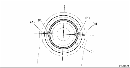
(a) | Put an alignment mark. | (b) | Split portion of bushing intermediate plate | (c) | Bushing intermediate plate |
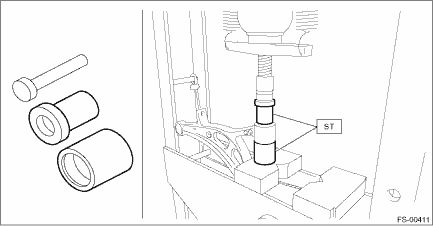
2. Using the ST and a press, remove the busing front - front arm.
PREPARATION TOOL:
ST: INSTALLER & REMOVER SET (927680000)
2. BUSHING REAR - FRONT ARM
1. Put an alignment mark on the front arm assembly based on the center of recess portion of the busing rear - front arm.
2. Using the ST and a press, remove the busing rear - front arm.
PREPARATION TOOL:
ST1: REMOVER (20299AG000)
ST2: BASE (20299AG010)
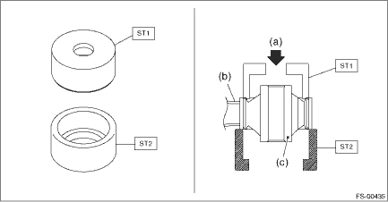
(a) | Press | (b) | Front arm ASSY | (c) | Bushing rear - front arm |
 Removal
FRONT SUSPENSION > Front ArmREMOVAL1. Lift up the vehicle, and then remove the front wheels.2. Remove the under cover - front. Front Under Cover > REMOVAL">3. Remove the front arm assem ...
 Installation
FRONT SUSPENSION > Front ArmINSTALLATION1. Before installation, inspect the following items and replace any faulty part with a new one.• Check the front arm assembly for damage or cracks, and ...
Other materials:
Warning chimes and warning indicator of the keyless access with push-button
start system (if equipped)
Access key warning indicator (type A)
Access key warning indicator (type B)
The warning chime and the access key
warning indicator are used for the following
purposes.
Minimizing improper operations when
using the keyless access with push-button
start system
Helping protect you ...
To increase the speed (by accelerator pedal)
1. Depress the accelerator pedal to
accelerate the vehicle to the desired
speed.
2. Press the "RES/SET" switch to the
"SET" side once. Now the desired speed
is set and the vehicle will keep running at
that speed without depressing the accelerator
pedal.
NOTE
U.S.-spec. models
If t ...
Dtc b1837 short in curtain airbag lh squib circuit (to ground)
AIRBAG SYSTEM (DIAGNOSTICS) > Diagnostic Chart with Trouble CodeDTC B1837 SHORT IN CURTAIN AIRBAG LH SQUIB CIRCUIT (TO GROUND)Diagnosis start condition:Ignition voltage is 10 V to 16 V.DTC detecting condition:• Curtain airbag harness (LH) circuit is shorted to ground.• Curtain airbag ...
