Subaru Crosstrek Service Manual: Installation
FRONT SUSPENSION > Front Arm
INSTALLATION
1. Before installation, inspect the following items and replace any faulty part with a new one.
• Check the front arm assembly for damage or cracks, and replace if defective.
• Visually check the bushing for abnormal cracks, fatigue or damage.
• Visually check the dust cover on the ball joint assembly for damage.
2. Using new self-locking nuts and flange bolts, temporarily tighten the front arm assembly to the front crossmember assembly.
3. Install the ball joint assembly to the housing assembly - front axle.
CAUTION:
Before tightening, make sure the bottom surface of the housing assembly - front axle and the stepped section of ball joint are in contact.
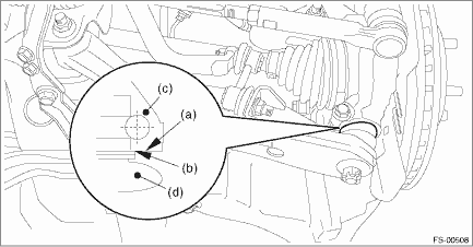
(a) | Bottom surface of housing ASSY - front axle | (c) | Housing ASSY - front axle | (d) | Ball joint ASSY |
(b) | Raised section of ball joint |
Tightening torque:
50 N·m (5.10 kgf-m, 36.9 ft-lb)
4. Install the stabilizer link.
Tightening torque:
60 N·m (6.12 kgf-m, 44.3 ft-lb)
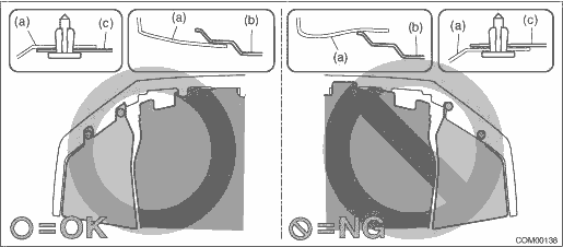
5. Install the under cover - front.
CAUTION:
Install so that the front end of the under cover (b) comes inside the bumper face - front (a), and the front end of the mud guard (c) comes outside the bumper face - front (a).
Tightening torque:
18 N·m (1.84 kgf-m, 13.3 ft-lb)
6. Install the front wheels.
Tightening torque:
Except for C4 model: 120 N·m (12.24 kgf-m, 88.5 ft-lb)
C4 model: 100 N·m (10.20 kgf-m, 73.8 ft-lb)
7. Unload the vehicle from the lift, and tighten the bolt which secures the front arm assembly to the front crossmember assembly while the wheels are in full contact with the ground and the vehicle is at curb weight.
Tightening torque:
Busing front - front arm: 95 N·m (9.7 kgf-m, 70.1 ft-lb)
Busing rear - front arm: 110 N·m (11.22 kgf-m, 81.1 ft-lb)
8. Inspect the wheel alignment and adjust if necessary.
• Inspection: Wheel Alignment > INSPECTION">
• Adjustment: Wheel Alignment > ADJUSTMENT">
CAUTION:
When the wheel alignment has been adjusted, perform the following VDC setting mode.
– Model without EyeSight: VDC sensor midpoint setting mode VDC Control Module and Hydraulic Control Unit (VDCCM&H/U) > ADJUSTMENT">
– Model with EyeSight: Neutral of Steering Angle Sensor & Lateral G Sensor 0 point setting VDC Control Module and Hydraulic Control Unit (VDCCM&H/U) > ADJUSTMENT">
– Model with EyeSight: Longitudinal G sensor & lateral G sensor 0 point setting VDC Control Module and Hydraulic Control Unit (VDCCM&H/U) > ADJUSTMENT">
9. Perform reinitialization of the auto headlight beam leveler system. (Model with auto headlight beam leveler) Auto Headlight Beam Leveler System > PROCEDURE">
 Disassembly
FRONT SUSPENSION > Front ArmDISASSEMBLY1. BUSHING FRONT - FRONT ARM1. Put an alignment mark on the front arm assembly based on the split portion of the bushing intermediate plate of the busing fron ...
 Front ball joint
...
Other materials:
Dtc p0134 a/f / o2 sensor circuit no activity detected bank 1 sensor 1
ENGINE (DIAGNOSTICS)(H4DO) > Diagnostic Procedure with Diagnostic Trouble Code (DTC)DTC P0134 A/F / O2 SENSOR CIRCUIT NO ACTIVITY DETECTED BANK 1 SENSOR 1DTC detecting condition:Immediately at fault recognitionCAUTION:After servicing or replacing faulty parts, perform Clear Memory Mode Clear Mem ...
Reclining the seatback
Pull the reclining lever up and adjust the
seatback to the desired position. Then
release the lever and make sure the
seatback is securely locked into place.
The seatback placed in a reclined position
can spring back upward with force when
the lever is pulled. While operating the
lever ...
Dtc u0073 control module communication bus off
AUTO HEADLIGHT BEAM LEVELER SYSTEM (DIAGNOSTICS) > Diagnostic Procedure with Diagnostic Trouble Code (DTC)DTC U0073 CONTROL MODULE COMMUNICATION BUS OFFDetected when CAN line abnormality is detected.NOTE:Perform the diagnosis for LAN system. Basic Diagnostic Procedure > PROCEDURE"> ...
