Subaru Crosstrek Service Manual: Dtc b1660 passenger s airbag on indicator failure
AIRBAG SYSTEM (DIAGNOSTICS) > Diagnostic Chart with Trouble Code
DTC B1660 PASSENGER’S AIRBAG ON INDICATOR FAILURE
Diagnosis start condition:
Ignition voltage is 10 V to 16 V.
DTC detecting condition:
• Passenger’s airbag indicator is faulty.
• Airbag control module is faulty.
• Airbag main harness circuit is open or shorted.
• Body harness circuit is open.
CAUTION:
Before performing diagnosis, refer to “CAUTION” in “General Description”. General Description > CAUTION">
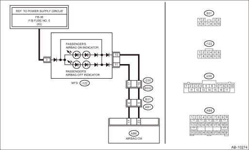
Wiring diagram:
Airbag system Airbag System > WIRING DIAGRAM">
| STEP | CHECK | YES | NO |
1.CHECK FOR POOR CONTACT.
1) Turn the ignition switch to OFF, disconnect the battery ground cable, and wait for 60 seconds or more.
2) Check that the connector between the airbag control module and MFD is securely connected.
Is there poor contact of any connector?
Repair the bulkhead harness. Or replace the airbag main harness along with body harness.
Diagnostic Chart with Trouble Code > DTC B1660 PASSENGER’S AIRBAG ON INDICATOR FAILURE">Go to Step 2.
2.CHECK AIRBAG MAIN HARNESS.
1) Disconnect the connectors (AB6, AB17, AB18) from airbag control module.
2) Connect the battery ground terminal and turn the ignition switch to ON.
NOTE:
Neither of ON/OFF illuminates when it is normal.
Does the passenger’s airbag indicator illuminate?
Diagnostic Chart with Trouble Code > DTC B1660 PASSENGER’S AIRBAG ON INDICATOR FAILURE">Go to Step 3.
Diagnostic Chart with Trouble Code > DTC B1660 PASSENGER’S AIRBAG ON INDICATOR FAILURE">Go to Step 4.
3.CHECK AIRBAG MAIN HARNESS.
1) Turn the ignition switch to OFF, disconnect the battery ground cable, and wait for 60 seconds or more.
2) Remove the MFD and disconnect the connector (i122).
3) Connect the connector (1AG) in the test harness AG to the connectors (AB6, AB17, AB18).
4) Measure the resistance between connector (2AG) in the test harness AG and chassis ground.
Connector & terminal
(2AG) No. 9 — (2AG) No. 8:
(2AG) No. 9 — Chassis ground:
(2AG) No. 8 — Chassis ground:
Is the resistance 1 M? or more?
Replace the MFD. Multi-function Display (MFD) > REMOVAL">
Repair the bulkhead harness. Or replace the airbag main harness along with body harness.
4.CHECK AIRBAG MAIN HARNESS.
1) Turn the ignition switch to OFF, disconnect the battery ground cable, and wait for 60 seconds or more.
2) Disconnect the connectors (AB6, AB17, AB18) from the airbag control module, and connect the connector (1AH) in the test harness AH.
3) Connect the connector (2AH) in the test harness AH and the connector (1AG) in the test harness AG.
4) Connect the connectors (7AG) and (8AG) in the test harness AG.
5) Connect the battery ground terminal and turn the ignition switch to ON.
Does the passenger’s airbag indicator illuminate?
Replace the airbag control module. Airbag Control Module">
Diagnostic Chart with Trouble Code > DTC B1660 PASSENGER’S AIRBAG ON INDICATOR FAILURE">Go to Step 5.
5.CHECK AIRBAG MAIN HARNESS.
1) Turn the ignition switch to OFF, disconnect the battery ground cable, and wait for 60 seconds or more.
2) Remove the MFD and disconnect the connector (i122).
3) Measure the resistance between connector (2AG) in the test harness AG and connector (i122).
Connector & terminal
(2AG) No. 9 — (i122) No. 11:
(2AG) No. 8 — (i122) No. 10:
Is the resistance less than 10 ??
Diagnostic Chart with Trouble Code > DTC B1660 PASSENGER’S AIRBAG ON INDICATOR FAILURE">Go to Step 6.
Repair the bulkhead harness. Or replace the airbag main harness along with body harness.
6.CHECK BODY HARNESS.
1) Turn the ignition switch to ON.
2) Measure the voltage between connector (i122) and chassis ground.
Connector & terminal
(i122) No. 3 (+) — Chassis ground (−):
Is the voltage 10 V or more?
Replace the MFD. Multi-function Display (MFD) > REMOVAL">
Check the power supply circuit of MFD.
 Dtc b1655 front buckle switch rh failure
AIRBAG SYSTEM (DIAGNOSTICS) > Diagnostic Chart with Trouble CodeDTC B1655 FRONT BUCKLE SWITCH RH FAILURENOTE:Refer to “Occupant Detection System” for details on DTC B1655. Diagnostic P ...
 Dtc b1675 satellite safing sensor failure
AIRBAG SYSTEM (DIAGNOSTICS) > Diagnostic Chart with Trouble CodeDTC B1675 SATELLITE SAFING SENSOR FAILUREDiagnosis start condition:Ignition voltage is 10 V to 16 V.DTC detecting condition:• S ...
Other materials:
Installation
POWER ASSISTED SYSTEM (POWER STEERING) > Steering WheelINSTALLATIONCAUTION:• Before handling the airbag system components, refer to “CAUTION” of “General Description” in “AIRBAG SYSTEM”. General Description > CAUTION">• If the steering w ...
Inspection
BRAKE > Rear Disc RotorINSPECTION1. DISC ROTOR RUNOUT CHECK1. Check the hub unit COMPL - rear axle for free play and runout before the inspection of disc rotor runout limit. Rear Hub Unit Bearing > INSPECTION">2. Check the disc rotor runout.(1) Remove the caliper body assembly. Rear ...
Inspection
FRONT SUSPENSION > Front StrutINSPECTIONCheck the removed part for wear, damage and cracks, and then repair or replace it if defective.1. STRUT1. Check for oil leaks.2. Move the piston rod up and down to check that it operates smoothly without any hitch.3. Check the piston rod runout.Preparation ...
