
Subaru Ascent 2018-2026 Owner's Manual: Driver Monitoring System indicator/warning
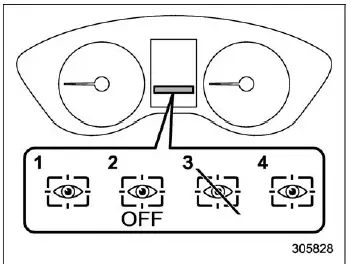
- Driver Monitoring System operation indicator light (green)
- Driver Monitoring System OFF indicator light
- Driver Monitoring System temporary stop indicator light
- Driver Monitoring System warning light (yellow)
In the Subaru Ascent, the Driver Monitoring System status is clearly communicated to the driver through dedicated indicators and warning lights displayed on the combination meter (color LCD). These visual signals provide real-time information about system activity, availability, and potential issues.
NOTE
When the Driver Monitoring System OFF indicator, temporary stop indicator, or warning light is illuminated in the Subaru Ascent, the system becomes unavailable. During this time, several personalization and user-related functions cannot be accessed.
- Register User
- Delete User
- Delete All Users
- Update Seat and Mirror Position
- Delete Driver Position
- Automatically Retract Seat on Entry
Driver Monitoring System operation indicator light (green)
When this green indicator is illuminated, it confirms that the Driver Monitoring System in the Subaru Ascent is actively operating and monitoring the driver as intended.
Driver Monitoring System OFF indicator light
This light appears when the Driver Monitoring System has been manually deactivated. In this state, the Subaru Ascent will not perform driver monitoring or recognition functions.
Driver Monitoring System temporary stop indicator light
This indicator signals that the system has temporarily paused operation. The Subaru Ascent may resume monitoring automatically once normal conditions are restored.
NOTE
The Driver Monitoring System in the Subaru Ascent may temporarily stop functioning under the following conditions:
- When the internal temperature of the system unit becomes excessively high or low
- When the system is unable to properly detect eye movement
- When facial features such as eyebrows, eyes, nose, or mouth cannot be clearly recognized
- When the camera or infrared LED components are obstructed, preventing accurate monitoring
Driver Monitoring System warning light (yellow)
If this yellow warning light appears, it indicates a malfunction within the Driver Monitoring System of the Subaru Ascent. In such cases, prompt inspection by a SUBARU dealer is strongly recommended to restore proper functionality.
 User recognition function
WARNING
Always complete registration, retrieval, or deletion of seat position and
outside mirror angle settings before starting to drive the Subaru Ascent. Attempting
to adjust or manage these pe ...
 Using the Driver Monitoring System
User recognition
When a driver profile is registered, the Subaru Ascent utilizes facial recognition
technology to automatically identify the driver and apply personalized settings.
1. When the ...
Other materials:
Installation
CONTINUOUSLY VARIABLE TRANSMISSION(TR580) > Drive PlateINSTALLATION1. Temporarily install the drive plate and reinforcement drive plate.NOTE:Align the knock pin hole of the crankshaft position sensor plate to the knock pin of the crankshaft to secure the knock pin.2. Set the ST.ST 498497300CRA ...
Installation
MECHANICAL(H4DO) > CamshaftINSTALLATION1. CAMSHAFT RHThe camshaft RH and cam carrier are designed as installing as a unit. Refer to “Cam Carrier” for installation procedures of camshaft RH. Cam Carrier > ASSEMBLY"> Cam Carrier > INSTALLATION">2. CAMSHAFT LHThe ...
Note
WIPER AND WASHER SYSTEMS > Wiper and Washer SystemNOTEFor procedure of each component of the wiper and washer system, refer to the respective sections.• Combination switch (wiper): Combination Switch (Wiper)">• Wiper blade: Wiper Blade">• Front wiper arm: Fron ...
