Subaru Crosstrek Service Manual: Door cord Location
WIRING SYSTEM > Door Cord
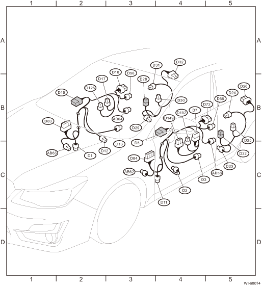
LOCATION
Connector | Connecting to | ||||
No. | Pole | Color | Area | No. | Description |
D1 | 8 | Black | C-2 | B30 | Bulkhead wiring harness |
D2 | 2 |
| C-4 | Front door speaker LH | |
D3 | 6 | Dark gray | C-4 | Front power window motor LH | |
D5 | 10 |
| B-4 | Outer mirror assembly LH | |
D7 | 16 |
| B-4 | Power window main switch | |
D11 | 8 | Black | C-4 | B101 | Bulkhead wiring harness |
D12 | 2 |
| B-2 | Front door speaker RH | |
D13 | 6 | Dark gray | B-3 | Front power window motor RH | |
D15 | 10 |
| B-2 | Outer mirror assembly RH | |
D17 | 8 |
| B-3 | Front power window sub-switch | |
D18 | 10 |
| B-3 | Front door lock actuator RH | |
D22 | 8 |
| B-5 | R10 | Rear wiring harness LH |
D23 | 2 |
| C-5 | Rear door speaker LH | |
D24 | 6 | Dark gray | B-5 | Rear power window motor LH | |
D25 | 8 |
| B-5 | Rear power window sub-switch LH | |
D26 | 10 |
| B-5 | Rear door lock actuator LH | |
D28 | 8 |
| B-3 | R13 | Rear wiring harness RH |
D29 | 2 |
| B-3 | Rear door speaker RH | |
D30 | 6 | Dark gray | B-4 | Rear power window motor RH | |
D31 | 8 |
| B-3 | Rear power window sub-switch RH | |
D32 | 10 |
| B-4 | Rear door lock actuator RH | |
D56 | 6 |
| B-3 | Outer handle RH | |
D66 | 6 |
| B-5 | Outer handle LH | |
D72 | 10 |
| B-5 | Front door lock actuator LH | |
D83 | 28 |
| B-2 | i76 | Instrument panel wiring harness |
D84 | 28 |
| C-3 | i101 | |
D102 | 3 |
| B-4 | Power window main switch | |
D125 | 5 |
| B-2 | Passenger’s seat door lock switch | |
D149 | 16 |
| C-4 | Remote control mirror switch | |
| |||||

Connector | Connecting to | ||||
No. | Pole | Color | Area | No. | Description |
AB58 | 2 | Yellow | C-5 | Front door impact sensor LH | |
AB62 | 2 | Yellow | C-3 | R123 | Rear wiring harness LH |
AB63 | 2 | Yellow | C-2 | R124 | Rear wiring harness RH |
AB64 | 2 | Yellow | B-3 | Front door impact sensor RH | |
| |||||
 Cvt control system Wiring diagram
WIRING SYSTEM > CVT Control SystemWIRING DIAGRAM ...
 Electric power steering system Wiring diagram
WIRING SYSTEM > Electric Power Steering SystemWIRING DIAGRAM ...
Other materials:
Installation
MECHANICAL(H4DO) > Cam SprocketINSTALLATION1. CAM SPROCKET RH• Intake cam sprocket RH1. Install the intake cam sprocket RH by aligning the knock hole (A) of intake cam sprocket RH and the knock pin (B) of intake camshaft RH.NOTE:Before installation, check that there is no foreign matter on ...
Inspection
HVAC SYSTEM (HEATER, VENTILATOR AND A/C) > Blower MotorINSPECTION1. Check the motor operation when battery voltage is applied between the terminals of motor.Terminal No.Inspection conditionsSpecificationConnection diagram2 (+) — 1 (−)Connect battery to the terminalsRotation2. If it does n ...
Caution
SPEED CONTROL SYSTEMS(H4DO) > General DescriptionCAUTION• Prior to starting work, pay special attention to the following:1. Always wear work clothes, a work cap, and protective shoes. Additionally, wear a helmet, protective goggles, etc. if necessary.2. Protect the vehicle using a seat cove ...
