Subaru Crosstrek Service Manual: Disassembly
DRIVE SHAFT SYSTEM > Front Drive Shaft
DISASSEMBLY
1. Place alignment marks on the shaft and outer race (PTJ).
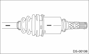
2. Remove the boot band and boot (PTJ).
CAUTION:
Be careful not to damage the boot.

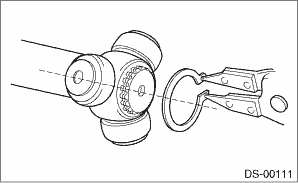
3. Remove the snap ring from outer race (PTJ).
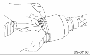
4. Remove the outer race (PTJ) from shaft assembly.
5. Wipe off grease.
CAUTION:
The grease is a special type of grease. Do not mix it with other grease.
6. Place alignment marks on the roller kit and trunnion.
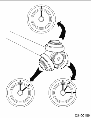
7. Remove the roller kit from trunnion.
CAUTION:
Be careful with the roller kit position.
8. Place alignment marks on the trunnion and shaft.
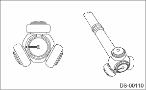
9. Remove the snap ring and trunnion.
CAUTION:
Be sure to wrap shaft splines with vinyl tape to protect the boot from scratches.
10. Remove the boot (PTJ).
11. Remove the O-ring from the groove of the shaft.
NOTE:
The EBJ is a non-disassembly part, so the axle disassembly stops here.
 Removal
DRIVE SHAFT SYSTEM > Front Drive ShaftREMOVAL1. Lift up the vehicle, and then remove the front wheels.2. Remove the axle nut.CAUTION:Do not loosen the axle nut while the front axle is loaded. Doing ...
 Inspection
DRIVE SHAFT SYSTEM > Front Drive ShaftINSPECTIONCheck the removed parts for damage, wear, corrosion etc. If faulty, repair or replace.• PTJ (pillow tripod joint)Check for seizure, corrosion, ...
Other materials:
Parking on a grade
Always block the wheels under both
vehicle and trailer when parking. Apply
the parking brake firmly. You should not
park on a hill or slope. If parking on a hill or
slope cannot be avoided, you should take
the following steps:
1. Apply the brakes and hold the pedal
down.
2. Have someone pl ...
Installation
SECURITY AND LOCKS > IG Relay2 (Push Button Start)INSTALLATIONCAUTION:Before handling the airbag system components, refer to “CAUTION” of “General Description” in “AIRBAG SYSTEM”. General Description > CAUTION">Install each part in the reverse order ...
Removal
FUEL INJECTION (FUEL SYSTEMS)(H4DO) > Fuel Level SensorREMOVALWARNING:Place “NO OPEN FLAMES” signs near the working area.CAUTION:• Be careful not to spill fuel.• If the fuel gauge indicates that two thirds or more of the fuel is remaining, be sure to drain fuel before star ...
