
Subaru Crosstrek Service Manual: Disassembly
CLUTCH SYSTEM > Clutch Pedal
DISASSEMBLY
1. Remove the clutch switches.
2. Remove the clip, assist spring, rod and bushing.
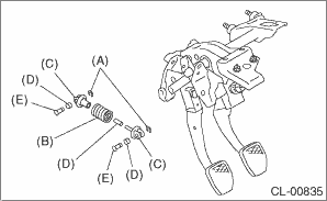
(A) | Clip |
(B) | Assist spring |
(C) | Assist rod |
(D) | Bushing |
(E) | Clevis pin |
3. Remove the spring pin and lever.
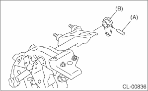
(A) | Spring pin |
(B) | Lever |
4. Remove the clutch pedal and pedal bushings.

(A) | Clutch pedal |
(B) | Pedal bushing |
5. Remove the stopper.
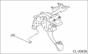
(A) | Stopper |
6. Remove the clutch pedal pad.
 Assembly
CLUTCH SYSTEM > Clutch PedalASSEMBLY1. Install the stopper and pedal pad to the clutch pedal.2. Install the clutch switch to the pedal bracket.3. Clean the pedal bushing holes of the clutch pedal a ...
 Inspection
CLUTCH SYSTEM > Clutch PedalINSPECTIONMove the clutch pedal pads in the lateral direction with a force of approximately 10 N (1 kgf, 2 lbf) to check that the clutch pedal deflection is within the s ...
Other materials:
Wiring diagram
SECURITY AND LOCKS > Push Button Start SystemWIRING DIAGRAMFor wiring diagrams related to the push button start system (ignition change), refer to the following items.• Keyless access system: Keyless Access System > WIRING DIAGRAM">• Push button start system: Push Button ...
Dtc p0138 o2 sensor circuit high voltage bank 1 sensor 2
ENGINE (DIAGNOSTICS)(H4DO) > Diagnostic Procedure with Diagnostic Trouble Code (DTC)DTC P0138 O2 SENSOR CIRCUIT HIGH VOLTAGE BANK 1 SENSOR 2DTC detecting condition:Detected when two consecutive driving cycles with fault occur.CAUTION:After servicing or replacing faulty parts, perform Clear Memory ...
Dtc b27a5 front internal antenna open
KEYLESS ACCESS WITH PUSH BUTTON START SYSTEM (DIAGNOSTICS) > Diagnostic Procedure with Diagnostic Trouble Code (DTC)DTC B27A5 FRONT INTERNAL ANTENNA OPENDTC detecting condition:When open circuit occurs in the harness between keyless access CM and front interior antenna.Trouble symptom:Keyless acc ...
