Subaru Crosstrek Service Manual: Compression Inspection
MECHANICAL(H4DO) > Compression
INSPECTION
CAUTION:
After warming-up, engine becomes very hot. Be careful not to burn yourself during measurement.
1. Turn the ignition switch to OFF.
2. After warming-up the engine, turn the ignition switch to OFF.
3. Make sure that the battery is fully charged.
4. Check the starter motor for satisfactory performance and operation.
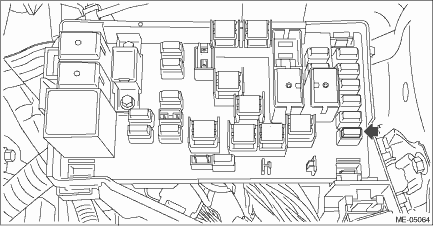
5. Remove the fuse of fuel pump from main fuse box.
6. Start the engine and run it until it stalls.
7. After the engine stalls, crank it for five more seconds.
8. Turn the ignition switch to OFF.
9. Remove all spark plugs. Spark Plug > REMOVAL">
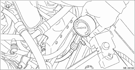
10. Install the compression gauge to the spark plug hole.
NOTE:
When using a screw-in type compression gauge, the screw should be less than 25 mm (0.98 in) long.
11. Connect the battery ground terminal. NOTE">
12. Turn the ignition switch to ON.
13. Depress the accelerator pedal to full throttle.
14. Crank the engine by starter motor and read the value when the needle of the compression gauge becomes stable.
NOTE:
• Perform at least two measurements per cylinder, and make sure that the values are correct.
• If the compression pressure is out of standard, check or adjust the pistons, valves and cylinders.
Compression pressure (at 200 — 300 r/min):
Standard
1,050 — 1,400 kPa (11 — 14 kg/cm2, 152 — 203 psi)
Difference between cylinders
100 kPa (1 kg/cm2, 14 psi) or less
15. After inspection, install the related parts in the reverse order of removal.
 Installation
MECHANICAL(H4DO) > V-beltINSTALLATION1. V-BELTInstall in the reverse order of removal.CAUTION:• When reusing the V-belt, wipe off dust and water with cloth.• Do not use the V-belt if th ...
 Connecting rod Specification
MECHANICAL(H4DO) > Connecting RodSPECIFICATIONRefer to “Cylinder Block” for removal and installation procedures of connecting rod. Cylinder Block > REMOVAL"> Cylinder Block ...
Other materials:
Installation
BRAKE > Rear Disc RotorINSTALLATIONNOTE:Before installation, remove mud and foreign matter from the caliper body assembly.1. Before installation, check the rear disc rotor. Rear Disc Rotor > INSPECTION">2. Install each part in the reverse order of removal.NOTE:When installing the rear ...
Dtc c2321 transmitter 1 function code abnormal
TIRE PRESSURE MONITORING SYSTEM (DIAGNOSTICS) > Diagnostic Procedure with Diagnostic Trouble Code (DTC)DTC C2321 TRANSMITTER 1 FUNCTION CODE ABNORMALNOTE:Refer to DTC C2324 for diagnostic procedure. Diagnostic Procedure with Diagnostic Trouble Code (DTC) > DTC C2324 TRANSMITTER 4 FUNCTION COD ...
Child restraint systems
Infants and small children should always
be placed in an infant or child restraint
system in the rear seat while riding in the
vehicle. You should use an infant or child
restraint system that meets Federal Motor
Vehicle Safety Standards or Canada
Motor Vehicle Safety Standards, is compatib ...
