Subaru Crosstrek Service Manual: Component
CONTROL SYSTEMS > General Description
COMPONENT
1. AT SELECT LEVER
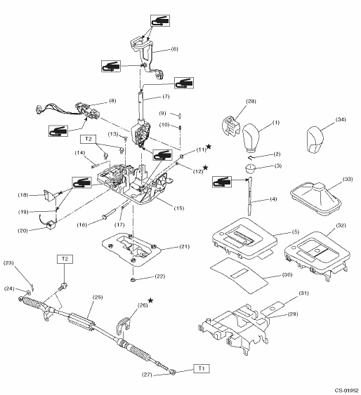
(1) | Grip sub ASSY (model with gate shifter) | (14) | Spacer pin guide | (27) | Nut |
(2) | Clamp grip pin | (15) | Plate COMPL | (28) | Button ASSY-AT |
(3) | Cover grip AT (model with gate shifter) | (16) | Shaft control | (29) | Housing |
(4) | Rod COMPL | (17) | Spacer pin guide | (30) | Blind A (model with gate shifter) |
(5) | Indicator cover (model with gate shifter) | (18) | Rod shift lock | (31) | Blind B (model with gate shifter) |
(6) | Arm COMPL | (19) | Cushion solenoid | (32) | Indicator assembly (model with boot shifter) |
(7) | Select lever COMPL | (20) | Solenoid unit | (33) | Boot ASSY (model with boot shifter) |
(8) | Plate guide | (21) | Gasket | (34) | Grip sub ASSY (model with boot shifter) |
(9) | Rod detent | (22) | Spacer plate | ||
(10) | Detent spring | (23) | Snap pin | Tightening torque: N·m (kgf-m, ft-lb) | |
(11) | Clamp push nut | (24) | Washer | T1: | 7.5 (0.8, 5.5) |
(12) | Clamp push nut | (25) | Select cable | T2: | 18 (1.8, 13.3) |
(13) | Clamp pin | (26) | Clamp | ||
2. 5MT GEAR SHIFT LEVER
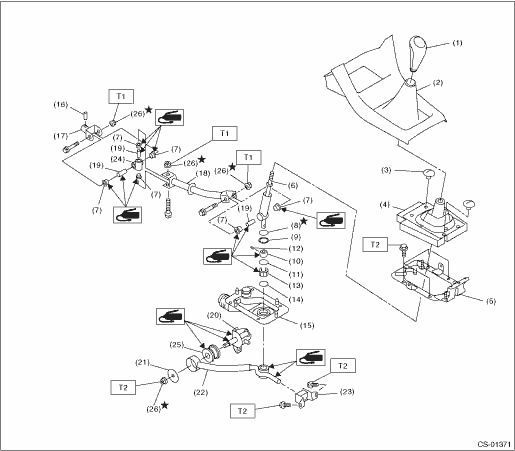
(1) | Gear shift knob | (11) | O-ring | (21) | Plate |
(2) | Console front cover ASSY | (12) | Spring pin | (22) | Stay |
(3) | Clamp | (13) | Bushing B | (23) | Cushion rubber |
(4) | Boot and insulator ASSY | (14) | O-ring | (24) | Boss |
(5) | Plate COMPL | (15) | Boot | (25) | Bushing |
(6) | Lever | (16) | Spring pin | (26) | Self-locking nut |
(7) | Bushing | (17) | Joint | ||
(8) | Lock wire | (18) | Rod | Tightening torque: N·m (kgf-m, ft-lb) | |
(9) | Snap ring | (19) | Spacer | T1: | 12 (1.2, 8.9) |
(10) | Bushing | (20) | Shift bracket | T2: | 18 (1.8, 13.3) |
 Specification
CONTROL SYSTEMS > General DescriptionSPECIFICATIONItemSpecificationsSwing torque of rod against leverN (kgf, lb)3.7 (0.38, 0.83) or less ...
 Preparation tool
CONTROL SYSTEMS > General DescriptionPREPARATION TOOL1. SPECIAL TOOLILLUSTRATIONTOOL NUMBERDESCRIPTIONREMARKS — SUBARU SELECT MONITOR 4Used for setting of each function and troubleshooting for el ...
Other materials:
Inspection
REAR SUSPENSION > Rear Shock AbsorberINSPECTION1. Check for oil leaks.2. Move the piston rod up and down to check that it operates smoothly without any hitch.3. Check the piston rod for play as follows:(1) Fix the outer shell in place and fully extend the rod.(2) Set the dial gauge on the end of ...
Caution
LUBRICATION(H4DO) > General DescriptionCAUTION• Prior to starting work, pay special attention to the following:1. Always wear work clothes, a work cap, and protective shoes. Additionally, wear a helmet, protective goggles, etc. if necessary.2. Protect the vehicle using a seat cover, fender ...
Removal
EXTERIOR/INTERIOR TRIM > Roof MoldingREMOVALCAUTION:Be careful not to damage the body.1. Remove the roof rail assembly. (model with roof rail) Roof Rail > REMOVAL">2. Turn over the front end of the molding - roof.3. Slide the inner fastener in the direction of the arrow using a flat t ...
