Subaru Crosstrek Service Manual: Bulkhead wiring harness (in engine compartment) Location
WIRING SYSTEM > Bulkhead Wiring Harness (In Engine Compartment)
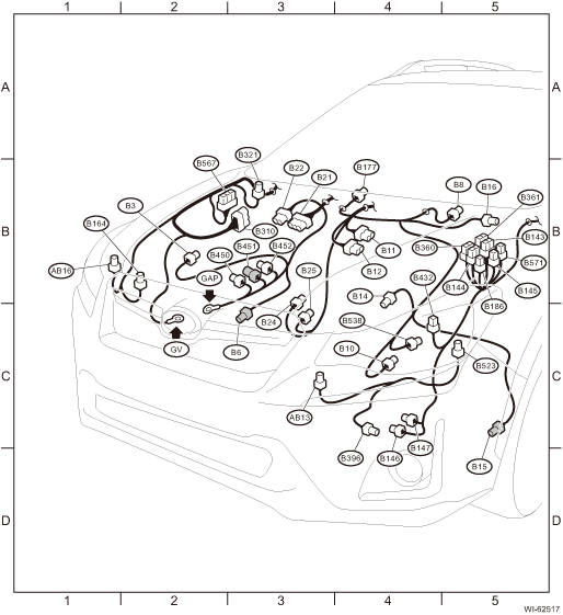
LOCATION
Connector | Connecting to | ||||
No. | Pole | Color | Area | No. | Description |
B3 | 5 | Black | B-2 | Mass air flow and intake air temperature sensor | |
B6 | 2 | Light gray | C-3 | Front ABS wheel speed sensor RH | |
B8 | 5 | Light gray | B-5 | Front wiper motor | |
B10 | 4 | Light gray | C-4 | Pressure switch | |
B11 | 12 | Light gray | B-4 | T4 | Transmission cord (CVT model) |
B12 | 16 | Dark gray | B-4 | T3 | |
B14 | 1 | Black | B-4 | Starter motor | |
B15 | 2 | Light gray | C-5 | Front ABS wheel speed sensor LH | |
B16 | 2 | Gray | B-5 | Brake fluid level switch | |
B21 | 54 | Black | B-3 | E2 | Engine wiring harness |
B22 | 16 | Brown | B-3 | ||
B24 | 2 | Gray | B-3 | T1 | Back-up light switch (MT model) |
B25 | 2 | Brown | C-3 | T2 | Neutral position switch 1 |
B143 | 20 |
| B-5 | M/B | |
B144 | 9 | Brown | B-5 | ||
B145 | 7 | Brown | B-5 | ||
B146 | 2 | Black | C-4 | Front washer motor | |
B147 | 2 | Gray | C-4 | Rear washer motor | |
B164 | 2 | Gray | B-2 | Keyless buzzer | |
B177 | 2 | Gray | B-4 | Wiper deicer | |
B186 | 8 |
| B-5 | M/B | |
B310 | 26 | Black | B-3 | VDC CM (with EyeSight) | |
38 |
| B-3 | VDC CM (without EyeSight) | ||
B321 | 2 | Black | B-3 | Hood switch | |
B360 | 16 | Gray | B-5 | F109 | Through joint connector |
B361 | 14 |
| B-5 | F108 | |
B396 | 2 | Brown | C-4 | Washer fluid level sensor | |
B432 | 8 | Black | C-4 | SBF holder | |
B450 | 10 | Black | B-3 | Power steering CM | |
B451 | 6 | Gray | B-3 | Torque sensor | |
B452 | 2 | Black | B-3 | Power steering CM | |
B523 | 2 | Light gray | C-5 | Battery temperature sensor | |
B538 | 3 | Black | C-4 | Battery current sensor | |
B567 | 26 |
| B-2 | Relay holder | |
B571 | 2 |
| B-5 | M/B | |
| |||||

Connector | Connecting to | ||||
No. | Pole | Color | Area | No. | Description |
AB13 | 2 | Yellow | C-3 | Front sub sensor LH | |
AB16 | 2 | Yellow | B-1 | Front sub sensor RH | |
| |||||
 Bulkhead wiring harness (in compartment) Location
WIRING SYSTEM > Bulkhead Wiring Harness (In Compartment)LOCATIONConnectorConnecting toNo.PoleColorAreaNo.DescriptionB274B-4 Blower Resistor (manual A/C)B308BlackC-5 Front door cord RHB3110GrayC-1AB ...
 Can communication system Wiring diagram
WIRING SYSTEM > CAN Communication SystemWIRING DIAGRAM ...
Other materials:
Dtc b2810 incompatible with eyesight (combination meter)
EyeSight (DIAGNOSTICS) > Diagnostic Procedure with Diagnostic Trouble Code (DTC)DTC B2810 INCOMPATIBLE WITH EyeSight (COMBINATION METER)Detected when the combination meter, which is not designed exclusively for EyeSight is installed.DTC DETECTING CONDITION:Incorrect specifications of combination ...
Removal
HVAC SYSTEM (HEATER, VENTILATOR AND A/C) > Air Vent GrilleREMOVAL1. CENTER GRILLE ASSEMBLYCAUTION:• Do not put your finger on the fin of the air vent grille. Doing so may damage the fin.• Always pull the center grille assembly toward you slowly. If attempting to remove by turning it u ...
Read diagnostic trouble code (dtc) Operation
TIRE PRESSURE MONITORING SYSTEM (DIAGNOSTICS) > Read Diagnostic Trouble Code (DTC)OPERATION1. On «Start» display, select «Diagnosis».2. On «Vehicle selection» display, input the target vehicle information and select «Confirmed».3. On «Main Menu» display, select «Each System».4. On «S ...
