Subaru Crosstrek Service Manual: Assembly
FRONT SUSPENSION > Front Strut
ASSEMBLY
1. Before assembly, check each part. Front Strut > INSPECTION">
2. Using a coil spring compressor, compress the coil spring - front.
CAUTION:
When installing the coil spring compressor to the coil spring, follow the operation manual accompanied with the coil spring compressor during operation.
NOTE:
Make sure that the vertical installation direction of the coil spring - front is as shown in the figure.
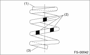
(1) | Diameter is small (upper part) |
(2) | Identification paint |
(3) | Diameter is large (bottom part) |
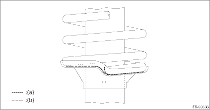
3. Set the front coil spring correctly so that its end face (a) contacts the vertical surface (b) of the spring seat - front strut UPR as shown in the figure.
4. Install the dust cover - inner and the helper - front strut to the piston rod.
5. Pull the piston rod fully upward, and install the spring seat.
NOTE:
Position the spring seat - front strut UPR as shown in the figure.
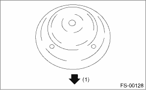
(1) | Outside of body |
6. Install the spacer - front strut and the strut mount - front to the piston rod, and temporarily tighten a new self-locking nut.
7. Using a hexagon wrench to prevent strut rod from turning, tighten the new self-locking nut with ST.
CAUTION:
Make sure that the strut mount - front turns smoothly after tightening.
Preparation tool:
ST: STRUT MOUNT SOCKET (20399AG000)
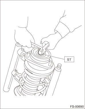
Tightening torque:
55 N·m (5.61 kgf-m, 40.6 ft-lb)
8. Loosen the coil spring compressor carefully.
 Front strut
...
 Removal
FRONT SUSPENSION > Front StrutREMOVAL1. Lift up the vehicle, and then remove the front wheels.2. Remove the front strut assembly.(1) Place an alignment mark (a) on the adjusting bolt and the strut. ...
Other materials:
Removal
DIFFERENTIALS > Rear Differential Front MemberREMOVAL1. Disconnect the ground cable from battery.2. Lift up the vehicle.3. Support the rear differential using transmission jack, and then remove the rear differential front member.(A)Rear differential front member ...
Inspection
SECURITY AND LOCKS > Keyless TransmitterINSPECTION1. KEYLESS TRANSMITTER BATTERY1. Check the keyless transmitter battery voltage.PREPARATION TOOL:Circuit testerNOTE:Complete the measurement within 5 seconds because the battery discharges during measurement.Battery terminalInspection ConditionsSta ...
Removal
CONTINUOUSLY VARIABLE TRANSMISSION(TR580) > Transmission Control Module (TCM)REMOVAL1. Disconnect the ground cable from battery. NOTE">NOTE:For model with battery sensor, disconnect the ground terminal from battery sensor.2. Remove the instrument panel lower cover. Instrument Panel Lowe ...
