Subaru Crosstrek Service Manual: Assembly
BRAKE > Rear Disc Brake Assembly
ASSEMBLY
1. Before installation, check each part. Rear Disc Brake Assembly > INSPECTION">
2. Clean the inside of the caliper body cylinder using brake fluid.
3. Apply a coat of brake fluid to piston seal and install the piston seal to the caliper body cylinder groove.
4. Apply a coat of brake fluid to the inner surface of caliper body cylinder and the entire outer surface of the piston - disc brake.
5. Apply grease contained in the piston seal kit to the piston boot, and install it to the groove at the end of the cylinder.
6. Insert the piston - disc brake into the caliper body cylinder.
CAUTION:
Do not force the piston - disc brake into the caliper body cylinder.
7. Position the piston boot in the grooves on the piston - disc brake and the caliper body cylinder.
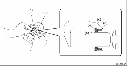
(a) | Piston - disc brake | (c) | Caliper body | (d) | Piston seal |
(b) | Piston boot |
8. Apply grease contained in the piston seal kit to the lock pin - rear brake, the outer surface of guide pin - rear brake, the inner surface of support cylinder, and the grooves of pin boot.
9. Install the pin boot to the lock pin - rear brake and guide pin - rear brake, and insert them into the support cylinder.
CAUTION:
Insert the lock pin - rear brake and guide pin - rear brake into specified position, and make sure that they slide and seat properly.
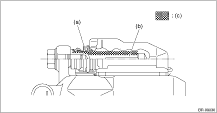
(a) | Pin boot | (b) | Lock pin - rear brake or guide pin - rear brake | (c) | Grease applied area |

 Removal
BRAKE > Rear Disc Brake AssemblyREMOVALCAUTION:Do not allow brake fluid to come in contact with the painted surface of the vehicle body. If it does, wash off with water and wipe away completely.1. ...
Other materials:
Alarm system
The alarm system helps to protect your
vehicle and valuables from theft. The horn
sounds and the hazard warning flashers
flash if someone attempts to break into
your vehicle.
For models with "keyless access with
push-button start system":
The system can be armed or disarmed
with the keyles ...
Disassembly
CLUTCH SYSTEM > Clutch PedalDISASSEMBLY1. Remove the clutch switches.2. Remove the clip, assist spring, rod and bushing.(A)Clip(B)Assist spring(C)Assist rod(D)Bushing(E)Clevis pin3. Remove the spring pin and lever.(A)Spring pin(B)Lever4. Remove the clutch pedal and pedal bushings.(A)Clutch pedal( ...
Read diagnostic trouble code (dtc) Operation
ENGINE (DIAGNOSTICS)(H4DO) > Read Diagnostic Trouble Code (DTC)OPERATION1. SUBARU SELECT MONITORNOTE:• For detailed operation procedures, refer to “Application help”.• For details concerning DTC, refer to “List of Diagnostic Trouble Code (DTC)”. List of Diagno ...
