Subaru Crosstrek Service Manual: Antenna cord Location
WIRING SYSTEM > Antenna Cord
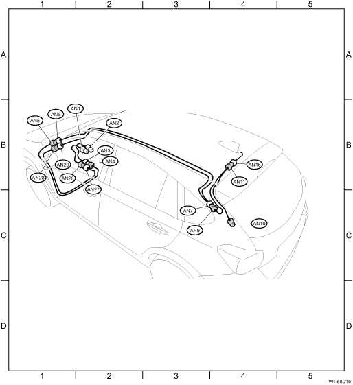
LOCATION
1. WITHOUT TELEMATICS
Connector | Connecting to | ||||
No. | Pole | Color | Area | No. | Description |
AN1 | 3 |
| B-2 | Audio | |
3 |
| B-2 | Navigation unit | ||
AN2 | 1 |
| B-2 | Audio | |
1 |
| B-2 | Navigation unit | ||
AN3 | 1 |
| B-2 | AN4 | Antenna cord |
AN4 | 1 |
| B-2 | AN3 | |
AN5 | 1 |
| B-1 | AN6 | |
AN6 | 1 |
| B-1 | AN5 | |
AN7 | 3 |
| C-3 | AN9 | |
AN9 | 3 |
| C-4 | AN7 | |
AN10 | 1 |
| C-4 | R97 | |
AN11 | 3 |
| B-4 | AN15 | Antenna |
AN15 | 3 |
| B-4 | AN11 | Antenna cord |
AN26 | 3 |
| B-2 | AN27 | |
AN27 | 3 | Gray | B-2 | AN26 | |
AN28 | 3 |
| B-1 | AN29 | |
AN29 | 3 |
| B-1 | AN28 | |
| |||||

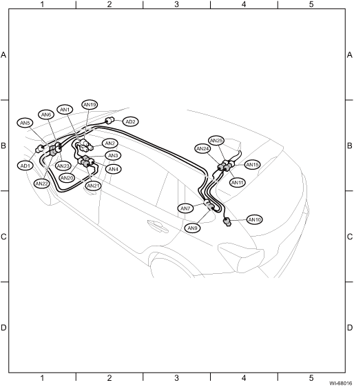
2. WITH TELEMATICS
Connector | Connecting to | ||||
No. | Pole | Color | Area | No. | Description |
AN1 | 3 |
| B-2 | Audio | |
3 |
| B-2 | Navigation unit | ||
AN2 | 1 |
| B-2 | Audio | |
1 |
| B-2 | Navigation unit | ||
AN3 | 3 |
| B-2 | AN4 | Antenna cord |
AN4 | 3 |
| B-2 | AN3 | |
AN5 | 3 |
| B-1 | AN6 | |
AN6 | 3 |
| B-1 | AN5 | |
AN7 | 3 | Blue | C-3 | AN9 | |
AN9 | 3 |
| C-3 | AN7 | |
AN10 | 1 |
| C-4 | R97 | |
AN11 | 3 |
| B-4 | AN15 | Antenna |
AN15 | 3 |
| B-4 | AN11 | Antenna cord |
AN19 | 1 |
| B-2 | Data communication module | |
AN20 | 1 |
| B-2 | AN21 | Antenna cord |
AN21 | 1 |
| B-2 | AN20 | |
AN22 | 1 |
| B-1 | AN23 | |
AN23 | 1 |
| B-1 | AN22 | |
AN24 | 1 |
| B-4 | AN25 | Telematics antenna |
AN25 | 1 |
| B-4 | AN24 | Antenna cord |
| |||||
Connector | Connecting to | ||||
No. | Pole | Color | Area | No. | Description |
AD1 | 8 |
| B-1 | B229 | Bulkhead wiring harness |
AD2 | 8 |
| B-2 | Telematics button | |
| |||||
 Airbag system Wiring diagram
WIRING SYSTEM > Airbag SystemWIRING DIAGRAM ...
 Audio system Wiring diagram
WIRING SYSTEM > Audio SystemWIRING DIAGRAM1. 6.2-INCH DISPLAY2. 7 INCH DISPLAY (WITHOUT TELEMATICS)3. 7 INCH DISPLAY (WITH TELEMATICS) ...
Other materials:
Caution
SPEED CONTROL SYSTEMS(H4DO) > General DescriptionCAUTION• Prior to starting work, pay special attention to the following:1. Always wear work clothes, a work cap, and protective shoes. Additionally, wear a helmet, protective goggles, etc. if necessary.2. Protect the vehicle using a seat cove ...
Read diagnostic trouble code (dtc) Operation
CONTINUOUSLY VARIABLE TRANSMISSION (DIAGNOSTICS) > Read Diagnostic Trouble Code (DTC)OPERATION1. On «Start» display, select «Diagnosis».2. On «Vehicle selection» display, input the vehicle information and select «Confirmed».3. On «Main Menu» display, select «Each System».4. On «Selec ...
Replacement
MANUAL TRANSMISSION AND DIFFERENTIAL(5MT) > Differential Side Retainer Oil SealREPLACEMENT1. Disconnect the ground cable from battery.2. Remove the front tires.3. Lift up the vehicle.4. Using the TORX® bit T70, remove the drain plug, and drain the transmission gear oil completely.CAUTION:• ...
