Subaru Crosstrek Service Manual: Adjustment
EXTERIOR BODY PANELS > Front Door
ADJUSTMENT
Adjust the clearance around the panel assembly - front door as follows.
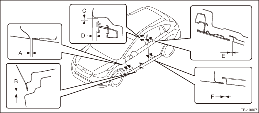
Part | Standard | |
A | Fender COMPL - front to Panel assembly - front door | 4.5±1.0 mm (0.18±0.04 in) |
B | Panel assembly - front door to Side sill | 6.0+1.5, −1.0 mm (0.24+0.06, −0.04 in) |
C | Roof panel to Front door sash | 5.1+1.5, −1.0 mm (0.20+0.06, −0.04 in) |
D | Surface level gap between roof panel and front door sash | 7±1.5 mm (0.28±0.06 in) |
E | Front door sash to Rear door sash | 5.5+1.5, −1.0 mm (0.22+0.06, −0.04 in) |
F | Panel assembly - front door to Panel assembly - rear door | 4.5±1.0 mm (0.18±0.04 in) |
1. Adjust the vertical and horizontal positions of the panel assembly - front door.
Preparation tool:
ST: WRENCH (925610000)
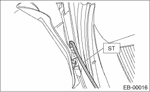
(1) Using ST, loosen the body side bolts of the upper hinge - front door and the lower hinge - front door.
(2) Adjust the vertical and horizontal clearance of the panel assembly - front door.
2. Adjust the surface level gap between the panel assembly - front door and the panel assembly - rear door.
CAUTION:
Do not use an impact wrench. Welding area on the striker nut plate is easily broken.
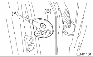
(1) Loosen the screws (A).
(2) Tap the striker - front door (B) using a plastic hammer to adjust the surface level gap between the rear end of the panel assembly - front door and the front end of the panel assembly - rear door.
 Front door
...
 Removal
EXTERIOR BODY PANELS > Front DoorREMOVAL1. FRONT DOOR PANEL1. Disconnect the ground cable from battery and wait for at least 60 seconds before starting work. NOTE">2. Remove the trim panel ...
Other materials:
Dtc p2127 throttle/pedal position sensor/switch "e" circuit low
ENGINE (DIAGNOSTICS)(H4DO) > Diagnostic Procedure with Diagnostic Trouble Code (DTC)DTC P2127 THROTTLE/PEDAL POSITION SENSOR/SWITCH "E" CIRCUIT LOWDTC detecting condition:Immediately at fault recognitionTrouble symptom:• Improper idling• Poor driving performanceCAUTION:After ...
Removal
CONTINUOUSLY VARIABLE TRANSMISSION(TR580) > Extension CaseREMOVAL1. Remove the transmission assembly from the vehicle. Automatic Transmission Assembly > REMOVAL">2. Remove the extension case and transmission hanger.NOTE:The total number of extension case mounting bolts is 13.3. Remove ...
Temporary spare tire
WARNING
Never attempt to tow a trailer when the temporary spare tire is installed
on your Subaru Ascent.
The temporary spare tire supplied with the Subaru Ascent is engineered
strictly for short-term emergency mobility and is not capable of handling the
additional load stress creat ...
