Subaru Crosstrek Owners Manual: Selection of manual mode

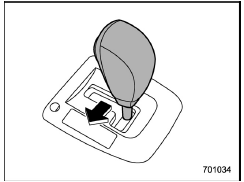
With the vehicle either moving or stationary, move the select lever from the "D" position to the "M" position to select the manual mode.

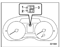
Type A
- Upshift indicator
- Downshift indicator
- Gear position indicator

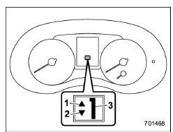
Type B
- Upshift indicator
- Downshift indicator
- Gear position indicator
When the manual mode is selected, the gear position indicator and upshift indicator and/or downshift indicator on the combination meter illuminate.
The gear position indicator shows the
currently selected gear in the 1st-to-6thgear
range. The upshift and downshift
indicators show when a gear shift is
possible. When the upshift indicator "
 "
illuminates, upshifting is possible. When
the downshift indicator "
  "
illuminates,
downshifting is possible. When both indicators
illuminate, upshifting and downshifting
are both possible. When the
vehicle stops (for example, at traffic
signals), the downshift indicator turns off.
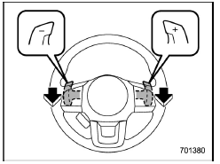
Gearshifts can be performed using the shift paddle behind the steering wheel.

To upshift to the next higher gear position, pull the shift paddle that has "+" indicated on it. To downshift to the next lower gear position, pull the shift paddle that has "-" indicated on it.
To deselect the manual mode, return the select lever to the "D" position from the "M" position.
CAUTION
Do not place or hang anything on the shift paddles. Doing so may result in accidental gear shifting.
NOTE
Please read the following points carefully and bear them in mind when using the manual mode.
- If you attempt to shift down when the engine speed is too high, i.e., when a downshift would push the tachometer needle beyond the red zone, beeps will be emitted to warn you that the downshift is not possible.
- If you attempt to shift up when the vehicle speed is too low, the transmission will not respond.
- You can perform a skip-shift (for example, from 4th to 2nd) by operating the shift paddle twice in rapid succession.
- The transmission automatically selects 1st gear when the vehicle stops moving.
- If the temperature of the transmission fluid becomes too high, the "AT OIL TEMP" warning light on the combination meter will illuminate. Immediately stop the vehicle in a safe location and let the engine idle until the warning light turns off.
 Select lever
Select lever positions
Select lever button
With the brake pedal depressed,
shift
while pressing the select lever button in.
Shift while pressing the select
lever
button in.
Shif ...
 Shift lock function
The shift lock function helps prevent the
improper operation of the select lever.
The select lever cannot be operated
unless the ignition switch is turned to the
"ON" position and the brake p ...
Other materials:
Activating and deactivating the alarm system
To change the setting of your vehicle's
alarm system for activation or deactivation,
do the following.
1. Disarm the alarm system. Refer to
"Disarming the system" 2-30.
2. Sit in the driver's seat and shut all
doors and the rear gate.
3. Turn the ignition switch to the "ON"
position.
...
Abs warning light does not go off
VEHICLE DYNAMICS CONTROL (VDC) (DIAGNOSTICS) > Warning Light Illumination PatternABS WARNING LIGHT DOES NOT GO OFFDetecting condition:• Defective combination meter• Defective CAN communicationTrouble symptom:ABS warning light does not go off when starting the engine.STEPCHECKYESNO1.RE ...
Dtc u1120 lost communication with autostart stop control module
KEYLESS ACCESS WITH PUSH BUTTON START SYSTEM (DIAGNOSTICS) > Diagnostic Procedure with Diagnostic Trouble Code (DTC)DTC U1120 LOST COMMUNICATION WITH AUTOSTART STOP CONTROL MODULEDetected when CAN data from hybrid system or Auto Start Stop CM is abnormal.NOTE:Perform the diagnosis for LAN system. ...
