Subaru Crosstrek Service Manual: Installation
WIPER AND WASHER SYSTEMS > Front Wiper Motor and Link
INSTALLATION
CAUTION:
• If the cowl panel assembly cannot be installed properly, do not hit or set it forcibly. The claws of the cowl panel or the windshield glass may be damaged.
• Before installing the windshield glass and cowl panel, make sure there are no gravel in the installing area.
1. Connect the battery ground terminal. NOTE">
2. To confirm that the motor assembly - windshield wiper is at the auto stop position, connect the harness to the motor and turn the wiper switch to ON/OFF once.
CAUTION:
During motor operation, do not touch the movable part.
3. Disconnect the ground cable from battery again. NOTE">
4. Install the motor assembly - windshield wiper.
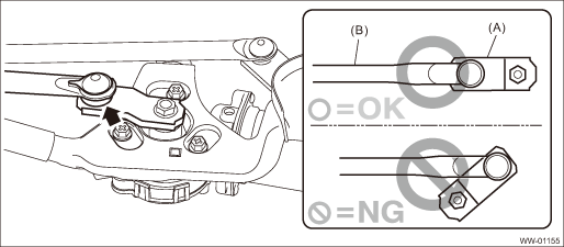
(1) Align the link plate position.
CAUTION:
Install the motor assembly - windshield wiper at the position where the rod (B) and link plate (A) are aligned in a straight line.
(2) Install the motor assembly - windshield wiper.
Tightening torque:
5.5 N·m (0.56 kgf-m, 4.1 ft-lb)
5. Install the cowl panel - side and the cowl panel assembly. Cowl Panel > INSTALLATION">
6. Install the arm assembly - windshield wiper. Front Wiper Arm > INSTALLATION">
7. Connect the battery ground terminal. NOTE">
8. Operate the windshield wiper to check that the stop position is aligned with the point mark.
If it is not aligned with the point mark, perform the removal and installation of the windshield wiper over again. Front Wiper Arm > REMOVAL">
9. Make sure that there is a gap of 1 mm (0.04 in) or more between the hose and the cover joint and between the hose and the joint washer hose during windshield wiper operation. (Models with EyeSight)
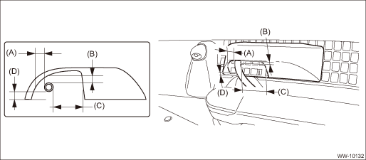
(A) | Gap between hose and cover joint outer side | (C) | Gap between hose and cover joint inner side | (D) | Gap between hose and cover joint lower side |
(B) | Gap between hose and cover joint upper side |
 Removal
WIPER AND WASHER SYSTEMS > Front Wiper Motor and LinkREMOVAL1. Disconnect the ground cable from battery. NOTE">2. Remove the arm assembly - windshield wiper. Front Wiper Arm > REMOVAL& ...

Other materials:
Dtc b1406 scu_eeprom
IMMOBILIZER (DIAGNOSTICS) > Diagnostic Procedure with Diagnostic Trouble Code (DTC)DTC B1406 SCU_EEPROMDTC DETECTING CONDITION:• Defective security control module• ROM of security control module cannot be accessedCAUTION:When the security control module is replaced, registration of th ...
List
TELEMATICS SYSTEM (DIAGNOSTICS) > Read Current DataLISTDisplayContentReference valueUnitTrip Count [count]Refer to “LAN SYSTEM (DIAGNOSTICS)”. General Description > CAUTION"> ŌĆö ŌĆö Count ŌĆö ŌĆö Time Count [msec] ŌĆö ŌĆö Current GPS DataCurrent GPS information ŌĆö ŌĆ ...
Removal
EXTERIOR/INTERIOR TRIM > Door TrimREMOVAL1. FRONT DOOR1. Disconnect the ground cable from battery. NOTE">2. Remove the trim panel - front door.(1) Attach the protective tape (a).(2) Open the cover and remove the screw.(3) Remove the clips, and remove the trim panel - front door from the ...
