Subaru Crosstrek Service Manual: Replacement
VEHICLE DYNAMICS CONTROL (VDC) > VDC Control Module and Hydraulic Control Unit (VDCCM&H/U)
REPLACEMENT
1. ONLY FOR MODELS WITHOUT EyeSight
CAUTION:
• Because the pressure sensor built into the H/U is easily damaged by static electricity, start the operation after performing static electricity measures.
• Be careful not to touch the sensors in the H/U to prevent damage.
• Because the seal of the VDCCM cannot be replaced, do not pull or peel it by lifting it up.
• Because the screw of the H/U will become slightly worn in every replacement procedure, 5 times is the maximum number for H/U re-use. If a problem is found such as not being able to torque the screw to specifications even before 5 replacement operations are performed, replace the H/U body.
• When installing the VDCCM, always use new screws.
• When the sealing surface of the VDCCM or H/U is dirty or damaged and it cannot be cleaned or repaired, replace with a new part.
1. Remove the VDCCM&H/U. VDC Control Module and Hydraulic Control Unit (VDCCM&H/U) > REMOVAL">
2. To prevent entry of foreign objects and brake fluid leakage, plug the oil pressure port of the VDCCM&H/U using a screw plug, etc.
3. Set the pump motor section of the removed VDCCM&H/U face down on a vise.
NOTE:
Before securing a part on a vise, place cushioning material such as wood blocks, aluminum plate, or cloth between the part and the vise.
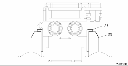
(1) | Aluminum plate, etc. | (2) | Vise |
4. Using TORX® E5, remove the four screws from VDCCM.
CAUTION:
Do not re-use the screws.
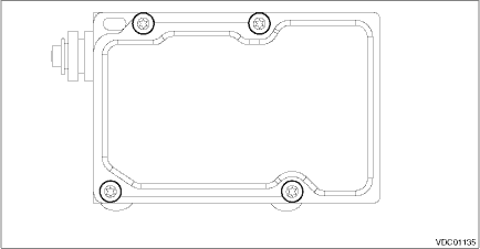
5. Slowly pull out the VDCCM upward from the H/U.
NOTE:
To prevent damaging of coil section, remove the VDCCM straight up from H/U without twisting.
6. Make sure there is no dirt or damage on the sealing surface of the H/U.
CAUTION:
• Do not clean the VDCCM&H/U by applying compressed air.
• Even if damage is found on the H/U seal, do not attempt repair by filing or with a metal scraper. To remove the seal residue, always use a plastic scraper. Do not use chemical such as paint thinner, etc., to clean.
7. Position the coil of the new VDCCM to align with the H/U valve.
8. To prevent deformation of the VDCCM housing cover, hold the corner of VDCCM and install it to the H/U without tilting.
9. Using TORX® E5, gradually tighten new screws in order of (1) through (4).
CAUTION:
Always use new screws.
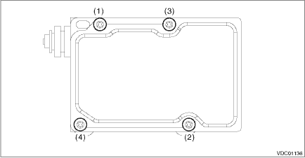
Tightening torque:
1.5 N·m (0.2 kgf-m, 1.1 ft-lb)
10. Check that there is no foreign matter in mating surface between the VDCCM&H/U.
11. Using TORX® E5 again, gradually tighten the screws in order of (1) through (4).
Tightening torque:
3.0 N·m (0.3 kgf-m, 2.2 ft-lb)
12. Check that there is no gap in the mating surface between VDCCM&H/U.
13. Install the VDCCM&H/U to the vehicle.
CAUTION:
When installing the VDCCM&H/U, replace the damper - hydraulic unit, spacer and nut with new parts.
14. Bleed air from the brake system. Air Bleeding > PROCEDURE">
15. Perform the selection and registration operation of parameter. Subaru Select Monitor > OPERATION">
NOTE:
• After replacing the VDCCM, be sure to perform the selection • registration operation of parameter.
• When the registration has not been performed, the DTC code “Parameter selection error” is detected together with the ABS/EBD/VDC warning light illumination.
16. Check the parameter to confirm that the applied models and grades of the relevant vehicle are included. Subaru Select Monitor > OPERATION">
17. If the applied model and grade of the target vehicle are not included, perform parameter selection and registration. Subaru Select Monitor > OPERATION">
18. Execute Clear Memory after parameter selection and registration operations because the DTC for “Parameter selection error” is memorized.
19. Perform “VDC sensor midpoint setting mode”. VDC Control Module and Hydraulic Control Unit (VDCCM&H/U) > ADJUSTMENT">
 Adjustment
VEHICLE DYNAMICS CONTROL (VDC) > VDC Control Module and Hydraulic Control Unit (VDCCM&H/U)ADJUSTMENT1. VDC SENSOR MIDPOINT SETTING MODE (MODELS WITHOUT EyeSight)After installing, replacing or a ...
 Inspection
VEHICLE DYNAMICS CONTROL (VDC) > VDC Control Module and Hydraulic Control Unit (VDCCM&H/U)INSPECTION1. Check the identification (a) of the VDC control module & hydraulic control unit (VDCCM ...
Other materials:
Vehicle finder function
Use this function to find your vehicle
parked among many vehicles in a large
parking lot. Provided you are within 30 feet
(10 meters) of the vehicle, pressing the
lock/arm button three times in a 5-second
period will cause your vehicle's horn to
sound once and its hazard warning flashers to fl ...
Dtc p0023 "b" camshaft position actuator control circuit/open bank 2
ENGINE (DIAGNOSTICS)(H4DO) > Diagnostic Procedure with Diagnostic Trouble Code (DTC)DTC P0023 "B" CAMSHAFT POSITION ACTUATOR CONTROL CIRCUIT/OPEN BANK 2DTC detecting condition:Immediately at fault recognitionTrouble symptom:Improper idlingCAUTION:After servicing or replacing faulty part ...
Removal
MECHANICAL(H4DO) > Crank SprocketREMOVALNOTE:When replacing a single part, perform the work with the engine assembly installed to body.1. Remove the chain cover. Chain Cover > REMOVAL">2. Remove the timing chain. Timing Chain Assembly > REMOVAL">3. Remove the crank sprocke ...
