
Subaru Crosstrek Service Manual: Dtc p0023 "b" camshaft position actuator control circuit/open bank 2
ENGINE (DIAGNOSTICS)(H4DO) > Diagnostic Procedure with Diagnostic Trouble Code (DTC)
DTC P0023 "B" CAMSHAFT POSITION ACTUATOR CONTROL CIRCUIT/OPEN BANK 2
DTC detecting condition:
Immediately at fault recognition
Trouble symptom:
Improper idling
CAUTION:
After servicing or replacing faulty parts, perform Clear Memory Mode Clear Memory Mode > OPERATION"> , and Inspection Mode Inspection Mode > PROCEDURE">.
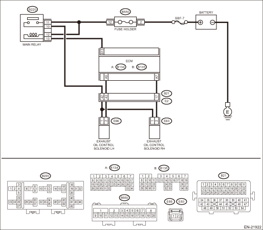
Wiring diagram:
Engine electrical system Power Supply Circuit">
| STEP | CHECK | YES | NO |
1.CHECK OUTPUT SIGNAL OF ECM.
1) Turn the ignition switch to ON.
2) Measure the voltage between ECM connector and chassis ground.
Connector & terminal
(B134) No. 5 (+) — Chassis ground (−):
Is the voltage 10 V or more?
Diagnostic Procedure with Diagnostic Trouble Code (DTC) > DTC P0023 "B" CAMSHAFT POSITION ACTUATOR CONTROL CIRCUIT/OPEN BANK 2">Go to Step 2.
Diagnostic Procedure with Diagnostic Trouble Code (DTC) > DTC P0023 "B" CAMSHAFT POSITION ACTUATOR CONTROL CIRCUIT/OPEN BANK 2">Go to Step 3.
2.CHECK FOR POOR CONTACT.
Check for poor contact of ECM connector.
Is there poor contact of ECM connector?
Repair the poor contact of ECM connector.
Even if DTC is detected, the circuit has returned to a normal condition at this time. Reproduce the failure, and then perform the diagnosis again.
NOTE:
In this case, temporary poor contact of connector, temporary open or short circuit of harness may be the cause.
3.CHECK POWER SUPPLY TO THE EXHAUST OIL CONTROL SOLENOID LH.
Measure the voltage between exhaust oil control solenoid LH connector and engine ground.
Connector & terminal
(E66) No. 1 (+) — Engine ground (−):
Is the voltage 10 V or more?
Diagnostic Procedure with Diagnostic Trouble Code (DTC) > DTC P0023 "B" CAMSHAFT POSITION ACTUATOR CONTROL CIRCUIT/OPEN BANK 2">Go to Step 4.
Repair the power supply circuit.
4.CHECK HARNESS BETWEEN ECM AND EXHAUST OIL CONTROL SOLENOID LH CONNECTOR.
1) Turn the ignition switch to OFF.
2) Disconnect the connector from ECM.
3) Disconnect the connector from the exhaust oil control solenoid LH.
4) Measure the resistance between exhaust oil control solenoid LH connector and engine ground.
Connector & terminal
(E66) No. 2 — Engine ground:
Is the resistance 1 M? or more?
Diagnostic Procedure with Diagnostic Trouble Code (DTC) > DTC P0023 "B" CAMSHAFT POSITION ACTUATOR CONTROL CIRCUIT/OPEN BANK 2">Go to Step 5.
Repair the short circuit to ground in harness between ECM connector and exhaust oil control solenoid LH connector.
5.CHECK HARNESS BETWEEN ECM AND EXHAUST OIL CONTROL SOLENOID LH CONNECTOR.
Measure the resistance of harness between ECM connector and exhaust oil control solenoid LH.
Connector & terminal
(B134) No. 5 — (E66) No. 2:
Is the resistance less than 1 ??
Diagnostic Procedure with Diagnostic Trouble Code (DTC) > DTC P0023 "B" CAMSHAFT POSITION ACTUATOR CONTROL CIRCUIT/OPEN BANK 2">Go to Step 6.
Repair the harness and connector.
NOTE:
In this case, repair the following item:
• Open circuit in harness between ECM connector and exhaust oil control solenoid LH connector
• Poor contact of coupling connector
6.CHECK EXHAUST OIL CONTROL SOLENOID LH.
Measure the resistance between exhaust oil control solenoid LH terminals.
Terminals
No. 1 — No. 2:
Is the resistance 6 — 12 ??
Repair the poor contact of exhaust oil control solenoid LH connector.
Replace the exhaust oil control solenoid LH. Oil Control Solenoid">
1. OUTLINE OF DIAGNOSIS
NOTE:
For the detection standard, refer to DTC P0013. Diagnostic Procedure with Diagnostic Trouble Code (DTC) > DTC P0013 "B" CAMSHAFT POSITION ACTUATOR CONTROL CIRCUIT/OPEN BANK 1">
 Dtc p0021 "a" camshaft position - timing over-advanced or system performance bank 2
ENGINE (DIAGNOSTICS)(H4DO) > Diagnostic Procedure with Diagnostic Trouble Code (DTC)DTC P0021 "A" CAMSHAFT POSITION - TIMING OVER-ADVANCED OR SYSTEM PERFORMANCE BANK 2DTC detecting condit ...
 Dtc p0024 "b" camshaft position - timing over-advanced or system performance bank 2
ENGINE (DIAGNOSTICS)(H4DO) > Diagnostic Procedure with Diagnostic Trouble Code (DTC)DTC P0024 "B" CAMSHAFT POSITION - TIMING OVER-ADVANCED OR SYSTEM PERFORMANCE BANK 2DTC detecting condit ...
Other materials:
Operation
VEHICLE DYNAMICS CONTROL (VDC) (DIAGNOSTICS) > Subaru Select MonitorOPERATION1. HOW TO USE SUBARU SELECT MONITORFor detailed operation procedures, refer to “Application help”.2. READ CURRENT DATA1. On «Start» display, select «Diagnosis».2. On «Vehicle selection» display, input t ...
Disassembly
FUEL INJECTION (FUEL SYSTEMS)(H4DO) > Intake ManifoldDISASSEMBLY1. Remove the throttle body. Throttle Body > REMOVAL">2. Remove the purge control solenoid valve. Purge Control Solenoid Valve > REMOVAL">3. Remove the manifold absolute pressure sensor. Manifold Absolute Pre ...
Preparation tool
AIRBAG SYSTEM (DIAGNOSTICS) > General DescriptionPREPARATION TOOLCAUTION:To measure the voltage and resistance of airbag system component, be sure to use the specified test harness.1. SPECIAL TOOL• SUBARU SELECT MONITORILLUSTRATIONTOOL NUMBERDESCRIPTIONREMARKS — SUBARU SELECT MONITOR 4Use ...
