Subaru Crosstrek Service Manual: Removal
AIRBAG SYSTEM > Curtain Airbag Sensor
REMOVAL
1. CROSSTREK MODEL
CAUTION:
• Before handling the airbag system components, refer to “CAUTION” of “General Description” in “AIRBAG SYSTEM”. General Description > CAUTION">
• Airbag system satellite safing sensor is located in the lower of the rear seat cushion center. Be careful not to apply strong impact to the sensor when working with the rear seat cushion removed.
1. Turn the ignition switch to OFF.
2. Disconnect the ground cable from battery and wait for at least 60 seconds before starting work. NOTE">
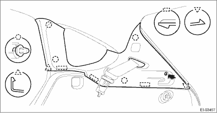
3. Remove the screws and clips, and remove the trim panel - rear quarter pillar UPR. (On the side where the curtain airbag sensor is removed)
4. Remove the rear seat cushion assembly. Rear Seat > REMOVAL">
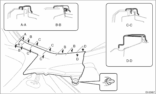
5. Release the clips and claws, and then remove the side sill cover - rear INN. (On the side where the curtain airbag sensor is removed)
CAUTION:
Do not pull with excessive force. Doing so may damage the claws of the side sill cover - rear INN.
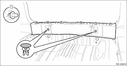
6. Remove the mat - rear floor CTR and the spacer - rear floor side.
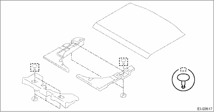
7. Remove the clips, and remove the trim panel - rear skirt.
8. Remove the trim panel - rear apron. (On the side where the curtain airbag sensor is removed)
(1) Remove the caps, and remove the bolts.
(2) Remove the screws.
(3) Disengage the clips, and remove the trim panel - rear apron.
NOTE:
For LH side, disconnect the connector of the luggage room light.
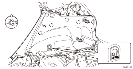
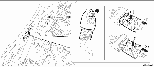
9. Remove the nuts and then remove the curtain airbag sensor. Airbag Connector > PROCEDURE">
 Installation
AIRBAG SYSTEM > Curtain Airbag SensorINSTALLATIONCAUTION:• Do not reuse the bolt and nut.Always replace with the specified new bolts and nuts.• When installing the sensor, insert the se ...

Other materials:
Dtc c0032 fr pressure reducing valve malfunction
VEHICLE DYNAMICS CONTROL (VDC) (DIAGNOSTICS) > Diagnostic Procedure with Diagnostic Trouble Code (DTC)DTC C0032 FR PRESSURE REDUCING VALVE MALFUNCTIONNOTE:For the diagnostic procedure, refer to “DTC C0064 NORMAL CLOSING VALVE 2 MALFUNCTION”. Diagnostic Procedure with Diagnostic Troub ...
Registering Bookmarks
You can register the music and artist now
being played in Bookmark.
1. Touch the tab.
2. Select the desired key. The following
items are appeared on the screen.
Item
Function
Track
When selected after the Bookmark
key is pressed, the current
track is bookmarked. ...
Dtc p0506 idle control system rpm - lower than expected
ENGINE (DIAGNOSTICS)(H4DO) > Diagnostic Procedure with Diagnostic Trouble Code (DTC)DTC P0506 IDLE CONTROL SYSTEM RPM - LOWER THAN EXPECTEDDTC DETECTING CONDITION:Detected when two consecutive driving cycles with fault occur.TROUBLE SYMPTOM:• Hard to start the engine.• Engine does not ...
