Subaru Crosstrek Service Manual: Removal
LIGHTING SYSTEM > Ignition Switch Illumination
REMOVAL
NOTE:
The ignition switch illumination is integrated into the immobilizer antenna assembly.
1. Disconnect the ground cable from battery. NOTE">
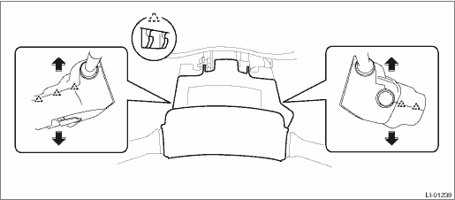
2. Remove the cover assembly - column.
(1) Remove the screws by turning the steering wheel to right and left.
(2) Release the claw, and remove the cover assembly - column UPR and the cover assembly - column LWR.
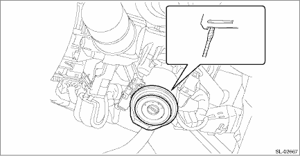
3. Remove the ignition switch illumination.
(1) Disconnect the connector.
(2) Release the claw using a flat tip screwdriver or similar tool wrapped with a protection tape, and remove the ignition switch illumination.
CAUTION:
Do not apply excessive force to remove the ignition switch illumination lock. Otherwise they may be broken because those parts are the products made of a plastic.
 Inspection
LIGHTING SYSTEM > Ignition Switch IlluminationINSPECTIONSTEPCHECKYESNO1.CHECK THE IGNITION SWITCH ILLUMINATION.Make sure the ignition switch illumination illuminates when driver’s side door i ...
 Installation
LIGHTING SYSTEM > Ignition Switch IlluminationINSTALLATIONInstall each part in the reverse order of removal. ...
Other materials:
Parking on a grade
Always block the wheels under both
vehicle and trailer when parking. Apply
the parking brake firmly. You should not
park on a hill or slope. If parking on a hill or
slope cannot be avoided, you should take
the following steps:
1. Apply the brakes and hold the pedal
down.
2. Have someone pl ...
Disassembly
CLUTCH SYSTEM > Master CylinderDISASSEMBLY1. Remove the straight pin and nipple.(A)Nipple(B)Straight pin2. Remove the oil seal.(A)Oil seal3. Move the seat towards the rear.(A)Seat(B)Master cylinder4. Remove the piston stop ring.CAUTION:When removing the piston stop ring, be careful to prevent the ...
Dtc b1677 satellite safing sensor initialization incomplete
AIRBAG SYSTEM (DIAGNOSTICS) > Diagnostic Chart with Trouble CodeDTC B1677 SATELLITE SAFING SENSOR INITIALIZATION INCOMPLETEDiagnosis start condition:Ignition voltage is 10 V to 16 V.DTC detecting condition:• Open or short circuit in harness of satellite safing sensor• Satellite safing ...
