Subaru Crosstrek Service Manual: Removal
HVAC SYSTEM (HEATER, VENTILATOR AND A/C) > Hose and Pipe
REMOVAL
1. LOW-PRESSURE HOSE
1. Using the refrigerant recovery system, discharge refrigerant. Refrigerant Recovery Procedure > PROCEDURE">
2. Remove the air intake boot. Air Intake Boot > REMOVAL">
CAUTION:
Move aside the air intake boot to perform the operation without disconnecting the PCV hose.
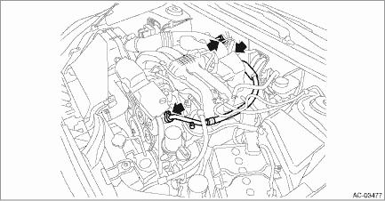
3. Remove the bolts and remove the hose - pressure suction.
CAUTION:
• Do not apply excessive force to the hose.
• Seal the disconnected hose, compressor and engaging part of expansion valve with a plug or vinyl tape to prevent foreign matter from entering.

2. HIGH-PRESSURE HOSE
1. Using the refrigerant recovery system, discharge refrigerant. Refrigerant Recovery Procedure > PROCEDURE">
2. Remove the reservoir tank. Reservoir Tank > REMOVAL">
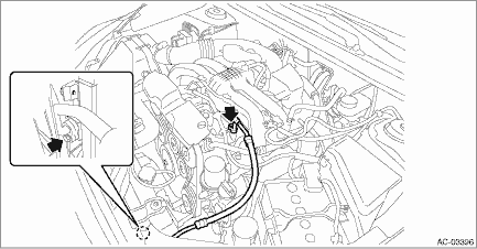
3. Remove the bolts, and remove the hose - pressure discharge.
CAUTION:
• Do not apply excessive force to the hose.
• Seal the disconnected hose, compressor and engaging part of compressor with a plug or vinyl tape to prevent foreign matter from entering.

3. A/C PIPE
1. Using the refrigerant recovery system, discharge refrigerant. Refrigerant Recovery Procedure > PROCEDURE">
2. Remove the battery. Battery > REMOVAL">
3. Remove the reservoir tank. Reservoir Tank > REMOVAL">
4. Remove the air intake boot.) Air Intake Boot > REMOVAL">
CAUTION:
Move aside the air intake boot to perform the operation without disconnecting the PCV hose.
5. Remove the pipe - evaporator cooling.
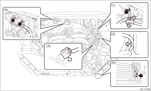
(1) Remove the cable clamps and bolts, and remove the battery cable stay.
(2) Disconnect the battery sensor harness from the main fuse box.
(3) Disconnect the pressure switch connector.
(4) Remove the bolts, and detach the hose - pressure suction from the expansion valve - cooling.
(5) Remove the bolts, and detach the pipe - evaporator cooling from the condenser assembly - air conditioner.

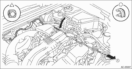
(6) Remove the pipe - evaporator cooling from the clip and expansion valve, and remove the pipe - evaporator cooling in numerical order as shown in the figure.
CAUTION:
• Do not apply excessive force to the pipe.
• Seal the engaging parts of disconnected pipe, hose, expansion valve and condenser with a plug or vinyl tape to prevent foreign matter from entering.
• Do not pull the harness and cable forcibly.

 Inspection
HVAC SYSTEM (HEATER, VENTILATOR AND A/C) > Hose and PipeINSPECTION1. Check the hoses for cracks, damage and expansion. Replace the hose if faulty.2. Check the pipes for crack or damage. Replace the ...
 Installation
HVAC SYSTEM (HEATER, VENTILATOR AND A/C) > Hose and PipeINSTALLATIONCAUTION:• If the hose and pipe have been replaced, add an appropriate amount of compressor oil to the compressor. Compress ...
Other materials:
Removal
BRAKE > Rear Disc RotorREMOVAL1. Lift up the vehicle, and then remove the rear wheels.2. Release the lever assembly - hand brake.3. Remove the caliper body assembly from the housing assembly - rear axle.(1) Remove the bolt from the brake hose bracket.(2) Remove the mounting bolt, and remove the c ...
Operation
POWER ASSISTED SYSTEM (POWER STEERING) (DIAGNOSTICS) > Subaru Select MonitorOPERATION1. HOW TO USE SUBARU SELECT MONITORFor detailed operation procedures, refer to “Application help”.2. READ CURRENT DATA1. On «Start» display, select «Diagnosis».2. On «Vehicle selection» display, ...
Disarming the system
Perform either of the following procedures.
Briefly press the disarm button (for less
than 2 seconds) on the access key/remote
transmitter.
Carry the access key and perform
either of the following procedures (models
with "keyless access with push-button
start system").
Grip the front door ...
