Subaru Crosstrek Service Manual: Removal
FUEL INJECTION (FUEL SYSTEMS)(H4DO) > Intake Manifold
REMOVAL
1. Release the fuel pressure. Fuel > PROCEDURE">
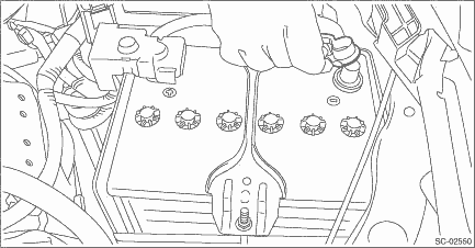
2. Disconnect the ground cable from battery.
3. Open the fuel filler lid and remove the fuel filler cap.
NOTE:
This operation is required to release the inner pressure of the fuel tank.
4. Lift up the vehicle.
5. Remove the under cover. Front Under Cover > REMOVAL">
6. Drain approximately 3.0 L (3.2 US qt, 2.6 Imp qt) of coolant. Engine Coolant > REPLACEMENT">
7. Remove the clip (A), and loosen the clamps (B) and (C) securing the air intake boot.
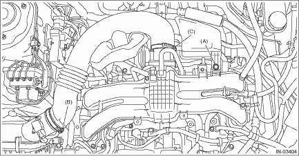
8. Remove the air intake boot from the air cleaner case (rear) and throttle body, and move the air intake boot aside so that it does not interfere with the work.
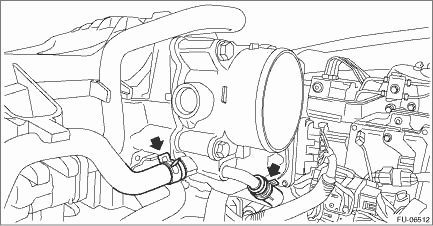
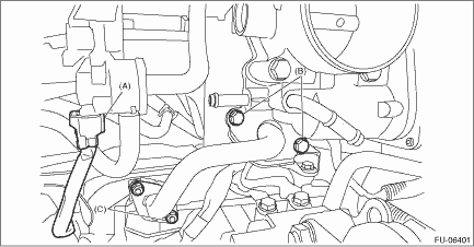
9. Disconnect the preheater hose from throttle body.
10. Disconnect the connector (A) from the purge control solenoid valve.
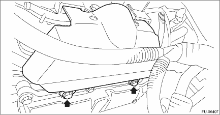
11. Loosen the bolt (B) which secures the EGR pipe to the intake manifold.
12. Remove the nut (C) which holds EGR pipe from the water pipe assembly.
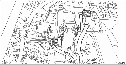
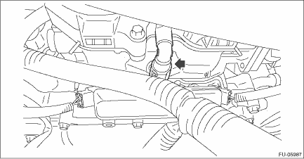
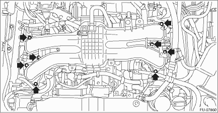
13. Disconnect the PCV hose (A) from intake manifold.
14. Disconnect the connector (B) from manifold absolute pressure sensor.
15. Disconnect the connector (C) from the throttle position sensor.
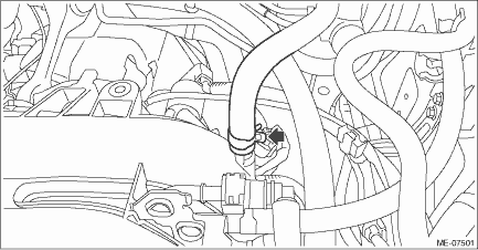
16. Disconnect the brake booster vacuum hose from the intake manifold.
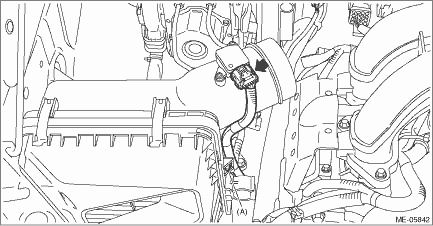
17. Disconnect the connector from the mass air flow and intake air temperature sensor, and remove the clip (A) securing the bulkhead wiring harness.
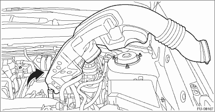
18. Remove the air cleaner case (rear) together with the air cleaner element.
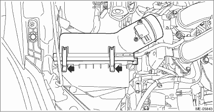
19. Remove the intake manifold protector RH.
20. Disconnect the fuel delivery pipe from the fuel pipe RH.
CAUTION:
• Be careful not to spill fuel.
• Catch the fuel from the pipes using a container or cloth.
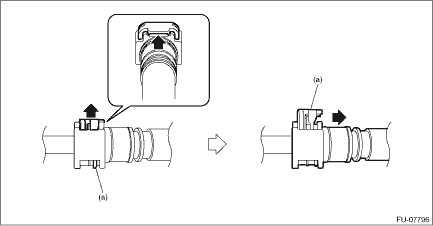
NOTE:
Disconnect the quick connector as shown in the figure.
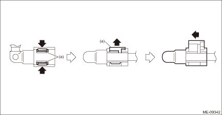
(a) | Slider |
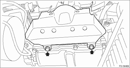
21. Remove the intake manifold protector LH.
22. Disconnect the fuel delivery pipe from the fuel pipe LH.
CAUTION:
• Be careful not to spill fuel.
• Catch the fuel from the pipes using a container or cloth.
NOTE:
Disconnect the quick connector as shown in the figure.
(a) | Slider |
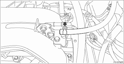
23. Disconnect the fuel delivery tube and evaporation hose.
CAUTION:
• Be careful not to spill fuel.
• Catch the fuel from the tubes using a container or cloth.
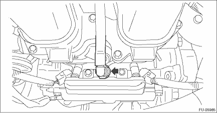
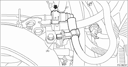
(1) Disconnect the quick connector on the fuel delivery tube from the fuel pipe assembly, and remove the clip (A) securing the fuel delivery tube.
NOTE:
Disconnect the quick connector as shown in the figure.
(a) | Slider |
(2) Disconnect the evaporation hose from the fuel pipe assembly.
24. Remove the intake manifold from the tumble generator valve assembly.
25. Remove the engine wiring harness. Engine Wiring Harness > REMOVAL">
 Assembly
FUEL INJECTION (FUEL SYSTEMS)(H4DO) > Intake ManifoldASSEMBLY1. Install the fuel pipe and cap to the intake manifold.Tightening torque:6.4 N·m (0.7 kgf-m, 4.7 ft-lb)2. Install the fuel deliv ...
 Disassembly
FUEL INJECTION (FUEL SYSTEMS)(H4DO) > Intake ManifoldDISASSEMBLY1. Remove the throttle body. Throttle Body > REMOVAL">2. Remove the purge control solenoid valve. Purge Control Solenoid ...
Other materials:
Driving tips
Always apply the foot or parking brake
when the vehicle is stopped in the "D" or
"R" position.
Make sure to apply the parking brake
when parking your vehicle. Do not hold
the vehicle with only the mechanical
friction of the transmission.
Do not keep the vehicle in a stationary
pos ...
Daylight saving time setting
1. Perform the preparation steps according
to "Preparation for date setting" 3-
56.
2. Operate the "
" or "
"
switch to
select the "Daylight Saving Time" item.
Then push the
button.
3. The current setting will be displayed.
Push the
button to enter the selection ...
Dtc p060b internal control module a/d processing performance
ENGINE (DIAGNOSTICS)(H4DO) > Diagnostic Procedure with Diagnostic Trouble Code (DTC)DTC P060B INTERNAL CONTROL MODULE A/D PROCESSING PERFORMANCENOTE:For the diagnostic procedure, refer to DTC P0606. Diagnostic Procedure with Diagnostic Trouble Code (DTC) > DTC P0606 CONTROL MODULE PROCESSOR&q ...
