
Subaru Crosstrek Service Manual: Removal
FUEL INJECTION (FUEL SYSTEMS)(H4DO) > Fuel Tank
REMOVAL
WARNING:
Place “NO OPEN FLAMES” signs near the working area.
CAUTION:
• Be careful not to spill fuel.
• Catch the fuel from the tubes using a container or cloth.
1. Release the fuel pressure. Fuel > PROCEDURE">
2. Drain fuel. Fuel > PROCEDURE">
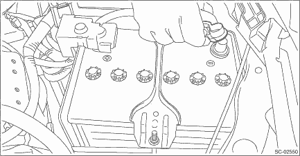
3. Disconnect the ground cable from battery.
4. Remove the rear seat cushion. Rear Seat > REMOVAL">
5. Remove the service hole cover of fuel pump.
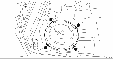
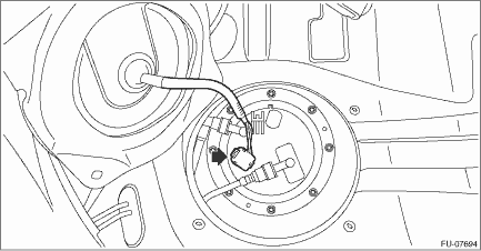
6. Disconnect connectors from the fuel pump, and move aside the service hole cover.
7. Remove the service hole cover of fuel sub level sensor.
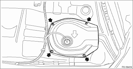
8. Disconnect connectors from the fuel sub level sensor, and move aside the service hole cover.
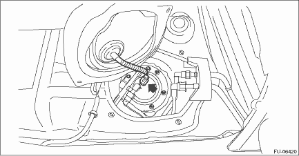
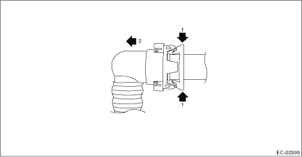
9. Disconnect the quick connector on the fuel delivery tube.
NOTE:
Disconnect the quick connector as shown in the figure.
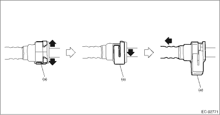
(a) | Slider |
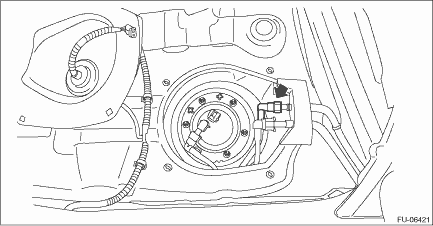
10. Lift up the vehicle.
11. Remove the rear exhaust pipe and muffler. Rear Exhaust Pipe > REMOVAL"> Muffler > REMOVAL">
12. Remove the rear differential. Rear Differential (T-type) > REMOVAL"> Rear Differential (VA-type) > REMOVAL">
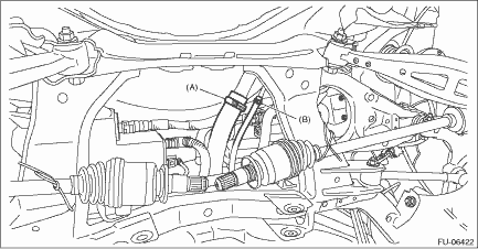
13. Disconnect the fuel filler hose (A) and evaporation hose (B) from the fuel filler pipe assembly.
14. Disconnect the vent tube from canister.
NOTE:
Disconnect the quick connector as shown in the figure.
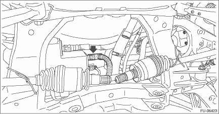
15. Remove the fuel tank protector. Fuel Tank Protector > REMOVAL">
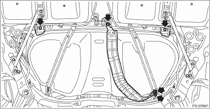
16. Remove the heat shield cover and stopper.
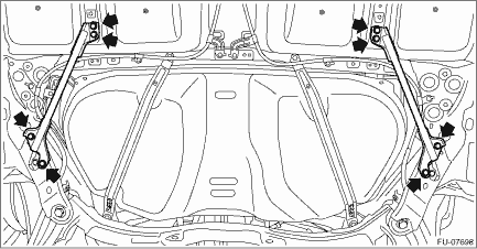
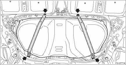
17. Remove the stay - rear frame COMPL.
18. Support the fuel tank with a transmission jack, remove the bolts from the fuel tank band, and remove the fuel tank from the vehicle.
WARNING:
• A helper is required to perform this work.
• Fuel may remain in the fuel tank. This will cause the left and right sides to be unbalanced. Be careful not to drop the fuel tank.
 Inspection
FUEL INJECTION (FUEL SYSTEMS)(H4DO) > Fuel TankINSPECTION1. Check that the fuel tank and fuel pipe have no deformation, cracks and other damages.2. Check that the fuel hose and tube have no cracks, ...
 Installation
FUEL INJECTION (FUEL SYSTEMS)(H4DO) > Fuel TankINSTALLATION1. Support the fuel tank with a transmission jack, set the fuel tank in place, and temporarily tighten the bolts of the fuel tank band.WAR ...
Other materials:
Inspection
COMMUNICATION SYSTEM > Horn SwitchINSPECTION1. CHECK HORN SWITCHCAUTION:Before handling the airbag system components, refer to “CAUTION” of “General Description” in “AIRBAG SYSTEM”. General Description > CAUTION">1. Turn the ignition switch to OFF.2 ...
Dtc p0716 input/turbine shaft speed sensor "a" circuit range/performance
CONTINUOUSLY VARIABLE TRANSMISSION (DIAGNOSTICS) > Diagnostic Procedure with Diagnostic Trouble Code (DTC)DTC P0716 INPUT/TURBINE SHAFT SPEED SENSOR "A" CIRCUIT RANGE/PERFORMANCEDTC detecting condition:Immediately at fault recognitionTrouble symptom:• No lock-up occurs.• Sho ...
Vehicle Dynamics Control operation indicator light
The indicator light flashes during activation
of the skid suppression function and
during activation of the traction control
function.
NOTE
The light may remain illuminated for
a short period of time after the engine
has been started, especially in cold
weather. This does not indicate ...
