Subaru Crosstrek Service Manual: Installation
FUEL INJECTION (FUEL SYSTEMS)(H4DO) > Fuel Tank
INSTALLATION
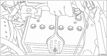
1. Support the fuel tank with a transmission jack, set the fuel tank in place, and temporarily tighten the bolts of the fuel tank band.
WARNING:
A helper is required to perform this work.
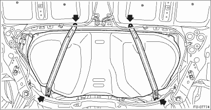
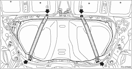
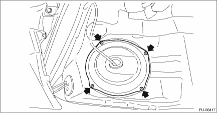
2. Tighten the bolts of the fuel tank band in the order shown in the figure.
Tightening torque:
33 N·m (3.4 kgf-m, 24.3 ft-lb)
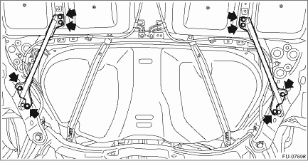
3. Install the stay - rear frame COMPL.
Tightening torque:
33 N·m (3.4 kgf-m, 24.3 ft-lb)
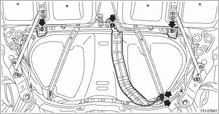
4. Install the heat shield cover and stopper.
Tightening torque:
18 N·m (1.8 kgf-m, 13.3 ft-lb)
5. Install the fuel tank protector. Fuel Tank Protector > INSTALLATION">
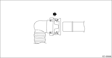
6. Connect the vent tube to the canister.
CAUTION:
• Check that there is no damage or dust on the quick connector. If necessary, clean the seal surface of the pipe.
• Make sure that the quick connector is securely connected.
NOTE:
Connect the quick connector as shown in the figure.
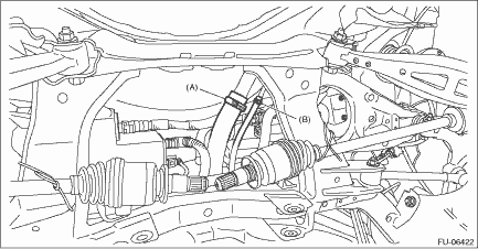
7. Securely insert the fuel filler hose (A) and evaporation hose (B) until the hose end contacts the spool, then attach the clamp or clip as shown in the figure.
Tightening torque:
2.5 N·m (0.3 kgf-m, 1.8 ft-lb)
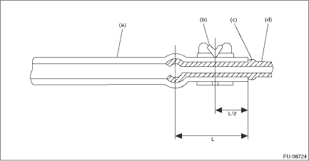
(a) | Hose | (c) | Spool or bump | (d) | Pipe |
(b) | Clamp or clip |
8. Install the rear differential. Rear Differential (T-type) > INSTALLATION"> Rear Differential (VA-type) > INSTALLATION">
9. Install the rear exhaust pipe and muffler. Rear Exhaust Pipe > INSTALLATION"> Muffler > INSTALLATION">
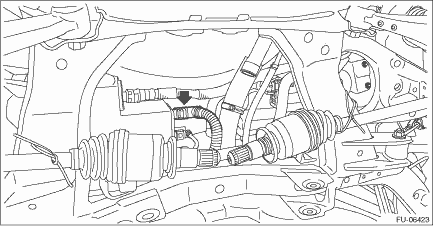
10. Connect the quick connector of the fuel delivery tube.
CAUTION:
• Check that there is no damage or dust on the quick connector. If necessary, clean the seal surface of the pipe.
• When connecting the quick connector, make sure to insert it all the way in before locking the slider.
• When it is difficult to lock the slider, check that the connector is fully inserted.
• After locking the slider, check again that the quick connector is securely connected.
NOTE:
Connect the quick connector as shown in the figure.
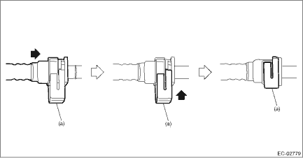
(a) | Slider |
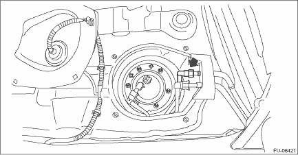
11. Connect the connector to the fuel sub level sensor.
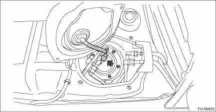
12. Install the service hole cover of fuel sub level sensor.
13. Connect the connector to the fuel pump.
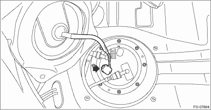
14. Install the service hole cover of fuel pump.
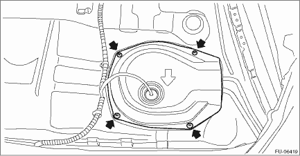
15. Install the rear seat cushion. Rear Seat > INSTALLATION">
16. Connect the battery ground terminal.
 Removal
FUEL INJECTION (FUEL SYSTEMS)(H4DO) > Fuel TankREMOVALWARNING:Place “NO OPEN FLAMES” signs near the working area.CAUTION:• Be careful not to spill fuel.• Catch the fuel from ...

Other materials:
Dtc c2522 resolver sensor
POWER ASSISTED SYSTEM (POWER STEERING) (DIAGNOSTICS) > Diagnostic Procedure with Diagnostic Trouble Code (DTC)DTC C2522 RESOLVER SENSORTrouble symptom:• The steering wheel operation feels heavy.• STEERING warning light illuminates.Wiring diagram:Electric power steering system Electri ...
Component
AIRBAG SYSTEM > General DescriptionCOMPONENT(1)Front sub sensor RH(4)Airbag warning light (in combination meter)(7)Airbag control module(2)Front sub sensor LH(5)Airbag ON/OFF indicator light (MFD)(8)Knee airbag module(3)Driver’s airbag module(6)Passenger’s airbag module(9)Steering rol ...
Starting the engine
NOTE
All vehicle doors (including rear gate)
and the engine hood must be closed
prior to activating the remote engine
start system. Any open entry point will
prevent starting or cause the engine to
stop.
The remote engine start system is activated
by pressing the fob button on your
remote e ...
