Subaru Crosstrek Service Manual: Removal
FUEL INJECTION (FUEL SYSTEMS)(H4DO) > Engine Wiring Harness
REMOVAL
1. Release the fuel pressure. Fuel > PROCEDURE">
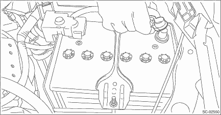
2. Disconnect the ground cable from battery.
3. Remove the intake manifold. Intake Manifold > REMOVAL">
4. Disconnect the connector from the engine.
• Structural diagram 1
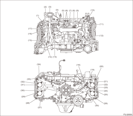
(1) | Tumble generator valve actuator RH | |
(2) | Engine harness connector (16P) | |
(3) | Engine harness connector (54P) | |
(4) | Throttle position sensor connector | |
(5) | Manifold absolute pressure sensor connector | |
(6) | Engine ground (2 locations) | |
(7) | Crankshaft position sensor | |
(8) | Knock sensor | |
(9) | Purge control solenoid valve connector | |
(10) | Tumble generator valve actuator LH | |
(11) | Fuel injector (#4) | |
(12) | Fuel injector (#2) | |
(13) | Engine coolant temperature sensor | |
(14) | Remove the clip from the screw hole. | |
(15) | Fuel injector (#1) | |
(16) | EGR valve | |
(17) | Fuel injector (#3) | |
(18) | Oil pressure switch | |
(19) | Engine oil temperature sensor | |
(20) | Intake camshaft position sensor LH | |
(21) | Intake oil control solenoid LH | |
(22) | Remove the clip from the screw hole. | |
(23) | Remove the clip from the screw hole. | |
(24) | Exhaust oil control solenoid LH | |
(25) | Remove the clip from the screw hole. | |
(26) | Exhaust camshaft position sensor LH | |
(27) | Remove the clip from the oval hole. | |
(28) | Exhaust camshaft position sensor RH | |
(29) | Remove the clip from the screw hole. | |
(30) | Exhaust oil control solenoid RH | |
(31) | Remove the clip from the screw hole. | |
(32) | Intake oil control solenoid RH | |
(33) | Intake camshaft position sensor RH | |
(34) | Remove the clip from the screw hole. | |
(35) | Oil level switch connector | |
• Structural diagram 2
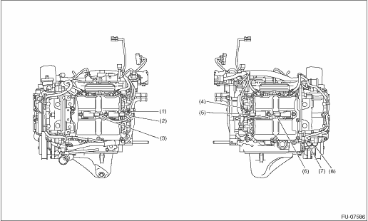
(1) | Remove the clip from the screw hole. | |
(2) | Ignition coil No. 4 | |
(3) | Ignition coil No. 2 | |
(4) | Remove the clip from the screw hole. | |
(5) | Ignition coil No. 3 | |
(6) | Ignition coil No. 1 | |
(7) | Front oxygen (A/F) sensor | |
(8) | Rear oxygen sensor | |
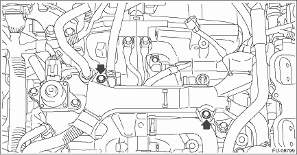
5. Remove the engine wiring harness.
 Inspection
FUEL INJECTION (FUEL SYSTEMS)(H4DO) > Engine Wiring HarnessINSPECTIONCheck that the engine wiring harness does not have deformation, cracks and any other damage. ...
 Installation
FUEL INJECTION (FUEL SYSTEMS)(H4DO) > Engine Wiring HarnessINSTALLATION1. Route the engine wiring harness around the engine and connect connectors.• Structural diagram 1(1)Tumble generator va ...
Other materials:
License plate light
1. The license plate light must be pushed
inwards, then pulled out to be removed.
2. Turn the bulb socket counterclockwise
and pull out the socket.
3. Pull the bulb out of the socket.
4. Install a new bulb.
5. Reinstall the bulb socket and the
license plate light cover. ...
Precautions against vehicle modification
WARNING
To avoid accidental activation of the
system or rendering the system
inoperative, which may result in
serious injury, no modifications
should be made to any components
or wiring of the SRS airbag system.
This includes following modifications.
Installation of custom steering
wh ...
Clear memory mode Operation
KEYLESS ACCESS WITH PUSH BUTTON START SYSTEM (DIAGNOSTICS) > Clear Memory ModeOPERATION1. On «Start» display, select «Diagnosis».2. On «Vehicle selection» display, input the target vehicle information and select «Confirmed».3. On «Main Menu» display, select «Each System».4. On «Selec ...
