Subaru Crosstrek Service Manual: Radar sensor
Adjustment
Blind Spot Detection/Rear Cross Traffic Alert > Radar Sensor
ADJUSTMENT
1. RADAR AXIS ADJUSTMENT
CAUTION:
• After removal/installation or replacement of the radar sensor, perform the radar axis adjustment.
• The procedure for the master is only shown here. However the procedure for the slave can also be done in the same way as the master.
1. Before performing the inspection, check the following items.
• The inflation pressure of tires is correct.
• The vehicle does not have load.
• Vehicle’s fuel tank is fully filled.
2. Place the vehicle on a level surface, where approximately 5 square meters (16.41 square ft) area can be secured behind the vehicle.
CAUTION:
• No metallic objects around the vehicle and on the floor in the area.
• Do not let in objects other than the radar reflector (ST), persons and metallic objects inside the area.
NOTE:
The illustration shows the secured area for adjusting the radar axis on the master side.
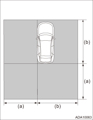
(a) | Approx. 4 m (13.12 ft) |
(b) | Approx. 5 m (16.41 ft) |
3. Prepare the Subaru Select Monitor, measure, leveling line, plumb bob, packing tape, RADAR REFLECTOR (ST), and stand or tripod for fixing the RADAR REFLECTOR.
Preparation tool:
ST: RADAR REFLECTOR (87699AL00A)
4. Set up the radar reflector.
NOTE:
The following procedure explains the method of setting the radar reflector so that the distance between radar reflector and radar sensor is 1,500 mm (4.92 ft) and the radar is positioned at an angle of 50 degree.
(1) Suspend the plumb bob from the center of the front hole cap, and mark the position where the plumb bob touches the ground. (Point A)
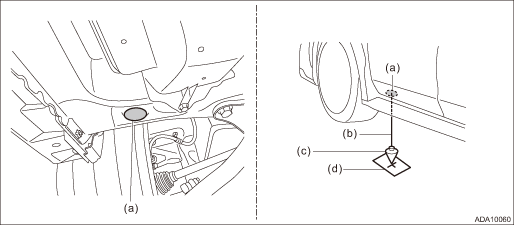
(a) | Front hole cap | (c) | Plumb bob | (d) | Point A |
(b) | Leveling line |
NOTE:
Stick the packing tape etc. on the floor, then make a marking on the tape.
(2) Suspend the plumb bob from the center of the rear hole cap, and mark the position where the plumb bob touches the ground. (Point B)
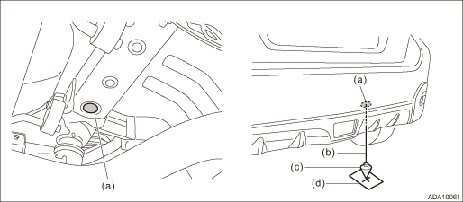
(a) | Rear hole cap | (c) | Plumb bob | (d) | Point B |
(b) | Leveling line |
NOTE:
Stick the packing tape etc. on the floor, then make a marking on the tape.
(3) Stretch a leveling line to draw an arc with the marked point A as a pivot.
(4) Stretch a leveling line to draw an arc with the marked point B as a pivot.
(5) Set up the radar reflector at the cross point.
CAUTION:
When setting up the radar reflector, adjust the height so that the center of the pyramid points at the radar sensor as shown in the figure.
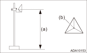
(a) | 751±10 mm (29.57±0.39 in) |
(b) | Center of pyramid |
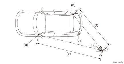
(a) | Point A | (c) | Radar reflector | (e) | 4,109 mm (13.48 ft) |
(b) | Point B | (d) | Radar sensor | (f) | 2,522 mm (8.27 ft) |
5. Connect the Subaru Select Monitor.
NOTE:
• Use the Subaru Select Monitor equipped with the latest version of the software.
• For detailed operation procedures, refer to “Application help”.
6. Turn the ignition switch to ON and wait for 10 seconds.
7. Perform radar axis adjustment.
(1) On «Start» display, select «Diagnosis».
(2) On «Vehicle selection» display, enter vehicle information and select «Confirmed».
(3) On «Main Menu» display, select «Each System».
(4) On «Select System» display, select «Subaru Rear Vehicle Detection(LH)» or «Subaru Rear Vehicle Detection(RH)» and then select «Enter».
(5) On «Select Function» display, select «Work Support».
(6) From the work support item list, select «RADAR Alignment».
(7) Follow the messages displayed on the Subaru Select Monitor screen when working.
NOTE:
Deviation of radar axis direction is indicated by + (plus) or − (minus).
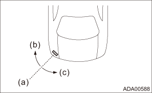
(a) | Center of radar |
(b) | + (plus) |
(c) | − (minus) |
(8) If the result is out of permissive range, it is assumed that the radar reflector position may be incorrect or the radar bracket or its installation location on the vehicle may be deformed. Check the set position of the radar reflector, radar bracket and other attachment, and perform the radar axis adjustment again.
Removal
Blind Spot Detection/Rear Cross Traffic Alert > Radar Sensor
REMOVAL
1. RADAR SENSOR LH (MASTER)
1. Disconnect the ground cable from battery. NOTE">
2. Remove the bumper face - rear. Rear Bumper > REMOVAL">
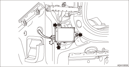
3. Remove the radar sensor LH (master).
(1) Disconnect the connector.
(2) Remove the nut and remove the radar sensor LH.
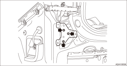
4. Remove the nut and remove the radar bracket.
2. RADAR SENSOR RH (SLAVE)
NOTE:
For the procedure of radar sensor RH (slave), refer to “RADAR SENSOR LH (MASTER)”.
 General description
Caution
Blind Spot Detection/Rear Cross Traffic Alert > General DescriptionCAUTION• Before disconnecting connectors of sensors or units, be sure to disconnect the ground cable from battery. ...
 Relay and fuse
Inspection
Blind Spot Detection/Rear Cross Traffic Alert > Relay and FuseINSPECTION1. CHECK FUSE1. Remove the fuse and inspect visually.2. If the fuse is blown out, replace the fuse.NOTE:If the fu ...
Other materials:
Removal
DRIVE SHAFT SYSTEM > Front Drive ShaftREMOVAL1. Lift up the vehicle, and then remove the front wheels.2. Remove the axle nut.CAUTION:Do not loosen the axle nut while the front axle is loaded. Doing so may damage the hub unit bearing.(1) Lift the crimped section of axle nut.(2) Remove the axle nut ...
Rear center seating position
CAUTION
The head restraint is not intended to
be used at the retracted position.
Before sitting on the seat, raise the
head restraint to the extended position.
Incorrect (retracted position)
Correct (extended position)
To raise:
Pull the head restraint up.
To lower:
Push ...
Inspection
CONTINUOUSLY VARIABLE TRANSMISSION(TR580) > Secondary Pressure SensorINSPECTION1. Start and warm up the engine.2. Depress the brake pedal, and shift the select lever to “D” range.3. Shift the select lever to “P” or “N” range.4. Depress the brake pedal and hold ...
