Subaru Crosstrek Service Manual: General description
Caution
Blind Spot Detection/Rear Cross Traffic Alert > General Description
CAUTION
• Before disconnecting connectors of sensors or units, be sure to disconnect the ground cable from battery. When replacing the electrical parts provided with memory functions that store contents specified by a customer, record the memory contents before disconnecting the battery ground cable.
• For precautions for Rear Vehicle Detection function, refer to “CAUTION” in “Blind Spot Detection/Rear Cross Traffic Alert (DIAGNOSTICS)” section. General Description > CAUTION">
Preparation tool
Blind Spot Detection/Rear Cross Traffic Alert > General Description
PREPARATION TOOL
1. SPECIAL TOOL
ILLUSTRATION | TOOL NUMBER | DESCRIPTION | REMARKS |
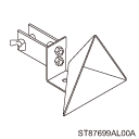
87699AL00A
RADAR REFLECTOR
Used for adjusting the radar axis of the radar sensor.
NOTE:
Attach the radar reflector to a round pole with a diameter of approx. 20 mm (0.79 in) or a 20-mm (0.79-in) square pole.

—
SUBARU SELECT MONITOR 4
Used for setting of each function and troubleshooting for electrical system.
NOTE:
For detailed operation procedures of Subaru Select Monitor 4, refer to “Application help”.
2. GENERAL TOOL
TOOL NAME | REMARKS |
Circuit tester | Used for measuring resistance, voltage and current. |
DST-i | Used together with Subaru Select Monitor 4. |
Measure (5 m (16 ft) or more) | Used for adjusting the radar axis of the radar sensor. |
Leveling line | |
Plumb bob | |
Packing tape | |
Stand, tripod, etc. |
 Wiring diagram
Blind Spot Detection/Rear Cross Traffic Alert > Blind Spot Detection/Rear Cross Traffic AlertWIRING DIAGRAMRefer to “Subaru Rear Vehicle Detection system” in the wiring diagram. Blind ...
 Radar sensor
Adjustment
Blind Spot Detection/Rear Cross Traffic Alert > Radar SensorADJUSTMENT1. RADAR AXIS ADJUSTMENTCAUTION:• After removal/installation or replacement of the radar sensor, perform the ...
Other materials:
Electrical specification
CONTROL SYSTEMS > AT Shift Lock Control SystemELECTRICAL SPECIFICATION• Model without push button ignition switchItemConnector No.Terminal No.Input/Output signalMeasured value and measuring conditionsBattery power supplyB28169 — 16 V7i846Ignition power supplyB2803210 — 15 V when ignitio ...
List
EyeSight (DIAGNOSTICS) > Diagnostic Code(s) DisplayLIST• List of Diagnostic Trouble Code (DTC)DTCItemContents of diagnosisReferenceU0073CONTROL MODULE COMMUNICATION BUS OFFDetected when bus off status (the stereo camera detects the failure and is disconnected from CAN line) occurs. Diagnost ...
Starting and stopping engine (models with push-button start system)
Safety precautions
Always follow the general safety recommendations provided for the Subaru Ascent
before operating the engine to ensure safe and reliable vehicle use.
Operating range for push-button start system
Refer to the specified operating range for the Subaru Ascent push-button start
...
