Subaru Crosstrek Service Manual: Power supply circuit Wiring diagram
WIRING SYSTEM > Power Supply Circuit
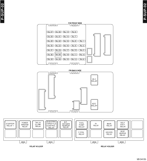
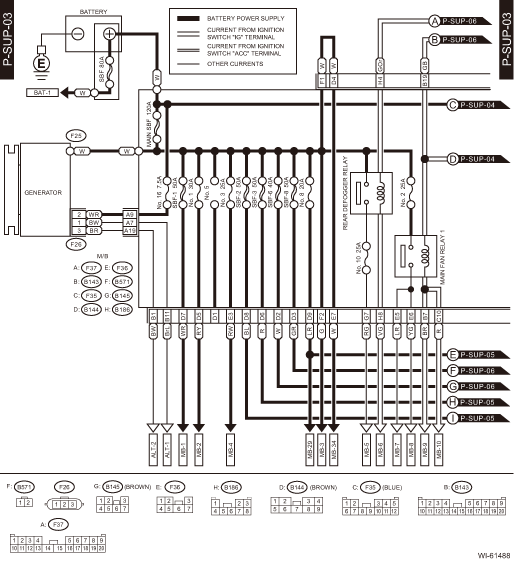
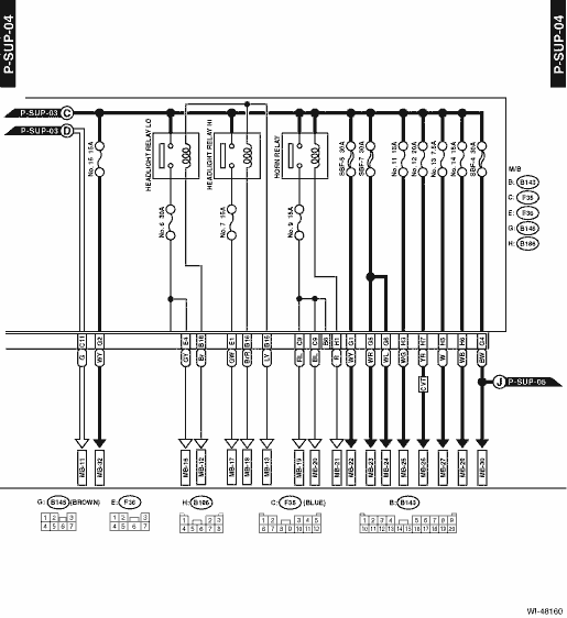
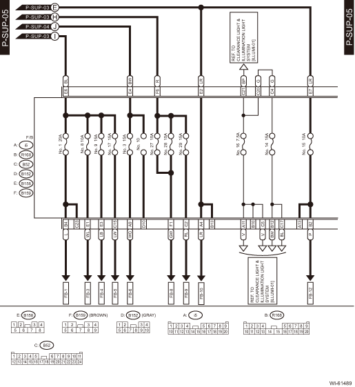
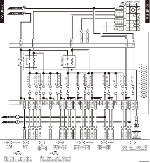
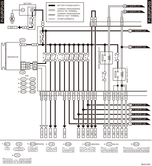
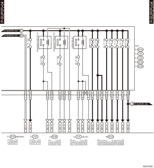
WIRING DIAGRAM
1. WITHOUT PUSH BUTTON START
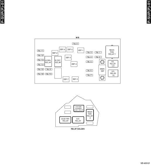
• Engine room side

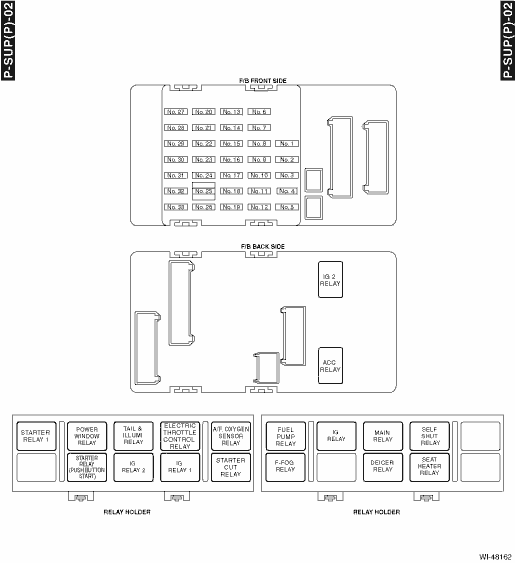
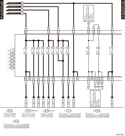
• Passenger room side
No. | Load |
MB-1 | VDC CM |
MB-2 | VDC CM |
MB-3 | Wiper relay |
MB-4 | Sub fan relay |
MB-5 | Mirror heater LH |
Mirror heater RH | |
Rear defogger | |
A/C control panel | |
MB-6 | Body integrated unit |
MB-7 | Main fan relay 2 |
MB-8 | Main fan motor |
MB-9 | ECM |
MB-10 | Main fan relay 2 |
MB-11 | Main fan relay 2 |
MB-12 | Body integrated unit |
MB-13 | Body integrated unit |
MB-16 | Front combination light LH |
Front combination light RH | |
MB-17 | Daytime running light relay |
MB-18 | Body integrated unit |
MB-19 | Horn |
MB-20 | Horn |
MB-21 | Horn switch |
Body integrated unit | |
MB-22 | A/F, oxygen sensor relay |
MB-23 | Main relay |
IG relay | |
MB-24 | Electronic throttle control relay |
MB-25 | Fuel pump relay |
MB-26 | TCM |
Self shut relay | |
MB-27 | ECM |
Data link connector | |
MB-28 | Key warning switch |
Turn signal and hazard unit | |
Body integrated unit | |
MB-29 | Spot map light |
Room light | |
Body integrated unit | |
Immobilizer antenna | |
MB-30 | Power window circuit breaker |
MB-32 | Tail & illumination relay |
Daytime running light relay | |
MB-34 | Data communication module |
ALT-1 | Combination meter |
ALT-2 | ECM |
ST-1 | Starter relay 1 |
Clutch start switch | |
ST-2 | Starter relay 1 |
FB-1 | Trailer connector |
FB-3 | Stop light and brake switch |
Brake relay | |
FB-4 | Wiper deicer relay |
FB-5 | Seat heater relay |
FB-6 | Body integrated unit |
FB-8 | Blower motor relay |
FB-9 | Front fog light relay |
Front fog light relay LH | |
Front fog light relay RH | |
FB-10 | Audio |
MFD | |
Navigation unit | |
FB-12 | Keyless entry CM |
TPMS & keyless entry CM | |
Luggage room light | |
FB-18 | Combination meter |
Body integrated unit | |
Impact sensor | |
Air mix door actuator LH (with left/right independent air conditioner) | |
Air mix door actuator RH (with left/right independent air conditioner) | |
Mode door actuator | |
Air mix door actuator (without left/right independent air conditioner) | |
Security CM | |
A/C control panel | |
Stereo camera | |
FB-19 | Remote control mirror switch |
FB-20 | Seat heater relay |
Rear view mirror | |
FB-21 | Rear accessory power supply socket |
FB-22 | Front accessory power supply socket |
FB-25 | Audio |
Navigation unit | |
AUX input terminal | |
Data communication module | |
FB-28 | A/C control panel |
FB-29 | Body integrated unit |
FB-30 | Radar sensor LH (master) |
Radar sensor RH (slave) | |
BSD/RCTA OFF switch | |
FB-32 | Clutch switch |
Impact sensor | |
Data link connector | |
Stop light and brake switch | |
Wiper deicer relay | |
Sunroof motor assembly | |
Sunroof switch | |
Sunroof switch (tilt) | |
FB-34 | Turn signal and hazard unit |
FB-35 | Inhibitor switch |
Back-up light switch | |
Auto headlight beam leveler CM | |
FB-36 | Combination meter |
MFD | |
FB-37 | Data communication module |
FB-38 | ECM |
TCM | |
Body integrated unit | |
Fuel pump relay | |
Stereo camera | |
FB-41 | Airbag CM |
FB-42 | Power window relay |
Wiper relay | |
FB-44 | VDC CM |
Steering angle sensor | |
Power steering CM | |
FB-45 | A/C control panel |
FB-46 | A/C relay |
Sub fan relay | |
Pressure switch | |
Blower motor relay | |
FB-47 | Occupant detection control module |
FB-48 | TPMS & keyless entry CM |
BAT-1 | Power steering CM |
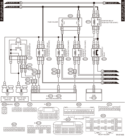
2. WITH PUSH BUTTON START
• Engine room side
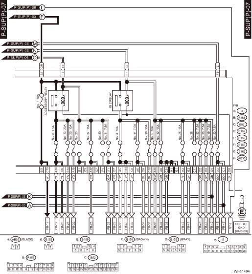
• Passenger room side
No. | Load |
MB-1 | VDC CM |
MB-2 | VDC CM |
MB-3 | Wiper relay |
MB-4 | Sub fan relay |
MB-5 | Mirror heater LH |
Mirror heater RH | |
Rear defogger | |
A/C control panel | |
MB-6 | Body integrated unit |
MB-7 | Main fan relay 2 |
MB-8 | Main fan motor |
MB-9 | ECM |
MB-10 | Main fan relay 2 |
MB-11 | Main fan relay 2 |
MB-12 | Body integrated unit |
MB-13 | Body integrated unit |
MB-16 | Front combination light LH |
Front combination light RH | |
MB-17 | Daytime running light relay |
MB-18 | Body integrated unit |
MB-19 | Horn |
MB-20 | Horn |
MB-21 | Horn switch |
Body integrated unit | |
MB-22 | A/F, oxygen sensor relay |
MB-23 | Main relay |
IG relay | |
MB-24 | Electronic throttle control relay |
MB-25 | Fuel pump relay |
MB-26 | TCM |
Self shut relay | |
MB-27 | ECM |
Data link connector | |
MB-28 | Turn signal and hazard unit |
Body integrated unit | |
MB-29 | Spot map light |
Room light | |
Body integrated unit | |
Immobilizer antenna | |
MB-30 | Power window circuit breaker |
MB-31 | Accessory relay |
IG relay 1 | |
IG relay 2 | |
MB-32 | Tail & illumination relay |
Daytime running light relay | |
MB-33 | Keyless access CM |
ID code box | |
MB-34 | Data communication module |
ALT-1 | Combination meter |
ALT-2 | ECM |
ST-2 | Starter relay 1 |
FB-1 | Trailer connector |
FB-3 | Stop light and brake switch |
Brake relay | |
FB-4 | Wiper deicer relay |
FB-5 | Seat heater relay |
FB-6 | Body integrated unit |
FB-7 | Remote engine start CM |
FB-8 | Blower motor relay |
FB-9 | Front fog light relay |
Front fog light relay LH | |
Front fog light relay RH | |
FB-10 | Audio |
MFD | |
Navigation unit | |
FB-12 | Keyless entry CM |
TPMS & keyless entry CM | |
Trunk room light | |
Luggage room light | |
FB-18 | Combination meter |
Body integrated unit | |
Impact sensor | |
Air mix door actuator LH (with left/right independent air conditioner) | |
Air mix door actuator RH (with left/right independent air conditioner) | |
Mode door actuator | |
Air mix door actuator (without left/right independent air conditioner) | |
Security CM | |
A/C control panel | |
Steering lock CM | |
Stereo camera | |
FB-19 | Remote control mirror switch |
FB-20 | Seat heater relay |
Rear view mirror | |
FB-21 | Rear accessory power supply socket |
FB-22 | Front accessory power supply socket |
FB-25 | Audio |
Navigation unit | |
AUX input terminal | |
Data communication module | |
FB-28 | A/C control panel |
FB-29 | Body integrated unit |
FB-30 | Radar sensor LH (master) |
Radar sensor RH (slave) | |
BSD/RCTA OFF switch | |
FB-32 | Impact sensor |
Data link connector | |
Stop light and brake switch | |
Wiper deicer relay | |
Sunroof motor assembly | |
Sunroof switch | |
Sunroof switch (tilt) | |
Remote engine start CM | |
FB-34 | Turn signal and hazard unit |
FB-35 | Inhibitor switch |
Back-up light switch | |
Auto headlight beam leveler CM | |
FB-36 | Combination meter |
MFD | |
FB-37 | Data communication module |
FB-38 | ECM |
TCM | |
Body integrated unit | |
Fuel pump relay | |
Keyless access CM | |
Stereo camera | |
FB-41 | Airbag CM |
FB-42 | Power window relay |
Wiper relay | |
FB-43 | Steering lock CM |
FB-44 | VDC CM |
Steering angle sensor | |
Power steering CM | |
FB-45 | A/C control panel |
FB-46 | A/C relay |
Sub fan relay | |
Pressure switch | |
Blower motor relay | |
FB-47 | Occupant detection control module |
FB-48 | TPMS CM |
BAT-1 | Power steering CM |
 Parking brake / brake fluid level warning light system Wiring diagram
WIRING SYSTEM > Parking Brake / Brake Fluid Level Warning Light SystemWIRING DIAGRAM ...
 Power window system Wiring diagram
WIRING SYSTEM > Power Window SystemWIRING DIAGRAM ...
Other materials:
24
CRUISE CONTROL SYSTEM (DIAGNOSTICS) > Diagnostic Procedure with Cancel Code24Malfunction in cruise control-related switch is detected.TROUBLE SYMPTOM:• Cruise control cannot be set. (Cancelled immediately.)• Cruise control cannot be released.Refer to DTC 11 for diagnostic procedure. D ...
Inspection
MECHANICAL(H4DO) > Cylinder BlockINSPECTION1. CYLINDER BLOCK & PISTON1. Visually inspect to make sure that there are no cracks, scratches or other damage.2. Use liquid penetrant tester on the important sections to check for fissures.3. Check that there are no traces of gas leaking or water le ...
Dtc b1813 short in driver s airbag dual stage - 2nd step circuit (to +b)
AIRBAG SYSTEM (DIAGNOSTICS) > Diagnostic Chart with Trouble CodeDTC B1813 SHORT IN DRIVER’S AIRBAG DUAL STAGE - 2ND STEP CIRCUIT (TO +B)Diagnosis start condition:Ignition voltage is 10 V to 16 V.DTC detecting condition:• Airbag main harness circuit is shorted to power supply.• A ...
