Subaru Crosstrek Service Manual: Operation
VEHICLE DYNAMICS CONTROL (VDC) > ABS Sequence Control
OPERATION
1. While the ABS sequence control is being performed, the operation of the hydraulic unit can be checked using the brake tester or pressure gauge after the hydraulic unit solenoid valve operation.
2. ABS sequence control can be started by the Subaru Select Monitor.
1. ABS SEQUENCE CONTROL WITH SUBARU SELECT MONITOR
NOTE:
In the event of any trouble, the ABS sequence control will not operate.
1. Connect the Subaru Select Monitor.
NOTE:
For detailed operation procedures, refer to “Application help”.
(1) Turn the ignition switch to ON.
(2) On «Start» display, select «Diagnosis».
(3) On «Vehicle selection» display, input the target vehicle information and select «Confirmed».
(4) On «Main Menu» display, select «Each System».
(5) On «Select System» display, select «Brake Control System» and select «Enter».
(6) On «Select Function» display, select «Work Support».
(7) From the work support item list, select «ABS Sequence Control Mode».
2. Follow the procedures displayed in the Subaru Select Monitor to execute the following.
(1) When using a brake tester, depress the brake pedal with a force of 100 N (10.2 kgf, 22.5 lbf).
(2) When using a pressure gauge, press the brake pedal so that the pressure gauge indicates 3,500 kPa (36 kgf/cm2, 511 psi).
3. The brake system being operated is displayed on the Subaru Select Monitor.
2. CONDITIONS FOR ABS SEQUENCE CONTROL
NOTE:
The control operation starts at point A.
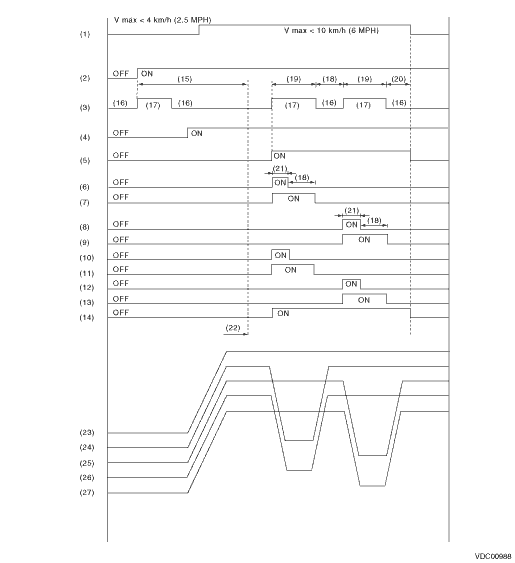
(1) | All wheel speed | (11) | RR compression valve | (20) | 0.6 seconds |
(2) | Ignition key | (12) | RL decompression valve | (21) | 0.4 seconds |
(3) | ABS warning light | (13) | RL compression valve | (22) | Point A |
(4) | Switch - stop light | (14) | Pump motor | (23) | Master cylinder pressure |
(5) | Valve relay | (15) | A few seconds | (24) | FL wheel cylinder pressure |
(6) | FL decompression valve | (16) | Light OFF | (25) | FR wheel cylinder pressure |
(7) | FL compression valve | (17) | Light ON | (26) | RR wheel cylinder pressure |
(8) | FR decompression valve | (18) | 1.0 second | (27) | RL wheel cylinder pressure |
(9) | FR compression valve | (19) | 1.4 seconds | ||
(10) | RR decompression valve |

 Specification
VEHICLE DYNAMICS CONTROL (VDC) > ABS Sequence ControlSPECIFICATION1. CONDITIONS FOR COMPLETION OF ABS SEQUENCE CONTROLWhen the following conditions develop, the ABS sequence control stops and ABS o ...
Other materials:
Basic diagnostic procedure Procedure
OCCUPANT DETECTION SYSTEM (DIAGNOSTICS) > Basic Diagnostic ProcedurePROCEDURESTEPCHECKYESNO1.CHECK WARNING LIGHT.Check whether the airbag warning light in the combination meter is lit.Does the airbag warning light illuminate? Basic Diagnostic Procedure > PROCEDURE">Go to Step 2.Perform ...
Dtc c1732 lateral g sensor
VEHICLE DYNAMICS CONTROL (VDC) (DIAGNOSTICS) > Diagnostic Procedure with Diagnostic Trouble Code (DTC)DTC C1732 LATERAL G SENSORDTC detecting condition:Defective lateral G sensorTrouble symptom:• ABS does not operate.• VDC does not operate.• Hill start assist does not operate.ST ...
Installation
ENTERTAINMENT > AntennaINSTALLATIONCAUTION:• After installing the center grille assembly, check that the air vent grille of the center grille assembly is inserted correctly into the air vent duct.• Before handling the airbag system components, always refer to “CAUTION” of ...
