Subaru Crosstrek Service Manual: Malfunction indicator light does not blink
ENGINE (DIAGNOSTICS)(H4DO) > Malfunction Indicator Light
MALFUNCTION INDICATOR LIGHT DOES NOT BLINK
DIAGNOSIS:
• The malfunction indicator light circuit is open or shorted.
• The delivery (test) mode fuse circuit is open.
TROUBLE SYMPTOM:
Malfunction indicator light does not blink during Inspection Mode.
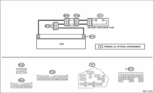
WIRING DIAGRAM:
Engine electrical system Engine Electrical System">
| STEP | CHECK | YES | NO |
1.CHECK STATUS OF MALFUNCTION INDICATOR LIGHT.
1) Turn the ignition switch to OFF.
2) Check the delivery (test) mode fuse is removed.
3) Turn the ignition switch to ON. (engine OFF)
Does the malfunction indicator light illuminate?
Malfunction Indicator Light > MALFUNCTION INDICATOR LIGHT DOES NOT BLINK">Go to Step 2.
Repair the malfunction indicator light circuit. Malfunction Indicator Light > MALFUNCTION INDICATOR LIGHT DOES NOT COME ON">
2.CHECK HARNESS BETWEEN ECM AND DELIVERY (TEST) MODE FUSE.
1) Turn the ignition switch to OFF.
2) Disconnect the connector from ECM.
3) Install the delivery (test) mode fuse.
CAUTION:
Do not use any fuses that are installed on the vehicle.
4) Measure the resistance of harness between ECM connectors.
Connector & terminal
(B137) No. 13 — (B137) No. 4:
Is the resistance less than 1 ??
Malfunction Indicator Light > MALFUNCTION INDICATOR LIGHT DOES NOT BLINK">Go to Step 3.
Repair the harness and connector.
NOTE:
In this case, repair the following item:
• Open circuit in harness between ECM connector
• Poor contact of each connector between ECM connector
3.CHECK FOR POOR CONTACT.
Check for poor contact of ECM connector.
Is there poor contact of ECM connector?
Repair the poor contact of ECM connector.
Replace the ECM. Engine Control Module (ECM)">
 Malfunction indicator light does not go off
ENGINE (DIAGNOSTICS)(H4DO) > Malfunction Indicator LightMALFUNCTION INDICATOR LIGHT DOES NOT GO OFFTROUBLE SYMPTOM:Although malfunction indicator light comes on when the engine runs, DTC is not sho ...
 Active test Operation
ENGINE (DIAGNOSTICS)(H4DO) > Active TestOPERATIONCAUTION:After executing the system operation check mode, execute the Clear Memory Mode. Clear Memory Mode > OPERATION">NOTE:• *: A ...
Other materials:
Inspection
INSTRUMENTATION/DRIVER INFO > Multi-function Display (MFD) SystemINSPECTION• Standard typeRefer to the following inspection steps. Multi-function Display (MFD) System > INSPECTION">• High grade typeRefer to “Basic Diagnostic Procedure” of “INSTRUMENTATION ...
How to change the source
The AUX operation screen can be
reached by the following methods:
Connect a portable audio device. Refer
to "Connecting and disconnecting a USB
memory/portable device"
Select the "AUX" key on the source
select screen. Refer to "Selecting an audio
source"
Audio level settings
You c ...
Dtc b1693 door sensor rh initialization incomplete
AIRBAG SYSTEM (DIAGNOSTICS) > Diagnostic Chart with Trouble CodeDTC B1693 DOOR SENSOR RH INITIALIZATION INCOMPLETEDiagnosis start condition:Ignition voltage is 10 V to 16 V.DTC detecting condition:• Open or short circuit in harness of side sensor bus (RH)• Front door impact sensor (RH ...
