Subaru Crosstrek Service Manual: Installation
AIRBAG SYSTEM > Front Sub Sensor
INSTALLATION
CAUTION:
• If the airbag has been activated, replace the front sub sensor with a new part.
• Do not reuse the bolt and nut.
Always replace with the specified new bolts and nuts.
• When installing the sensor, insert the set pin on the backside of the sensor into the hole on the body side securely.
1. Before installation, inspect the following items and replace any faulty part with a new part.
• Front sub sensor damage
• Connector damage
2. Install each part in the reverse order of removal.
CAUTION:
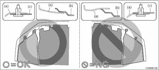
• Install so that the front end of the under cover (b) comes inside the bumper face - front (a), and the front end of the mud guard (c) comes outside the bumper face - front (a).
• Before installing the bumper face, match the claws on the bracket - front bumper with the engaging position of flange section on the bumper face side. If the engaging position is not correct, the flange section may be broken or the clearance between fender panel and bumper face may not be uniform.
Tightening torque:
Front sub sensor: 13 N·m (1.33 kgf-m, 9.6 ft-lb)
Bumper beam COMPL - front: 32 N·m (3.36 kgf-m, 24.3 ft-lb)
 Front sub sensor
...
 Removal
AIRBAG SYSTEM > Front Sub SensorREMOVALCAUTION:Before handling the airbag system components, refer to “CAUTION” of “General Description” in “AIRBAG SYSTEM”. Gen ...
Other materials:
Dtc b1650 occupant detection system malfunction
OCCUPANT DETECTION SYSTEM (DIAGNOSTICS) > Diagnostic Procedure with Diagnostic Trouble Code (DTC)DTC B1650 OCCUPANT DETECTION SYSTEM MALFUNCTIONDiagnosis start condition:Ignition voltage is 8 V to 16 V.DTC detecting condition:• Occupant detection sensor is faulty.• Occupant detection ...
Removal
CLUTCH SYSTEM > Release Bearing and LeverREMOVAL1. Remove the transmission assembly from the vehicle. Manual Transmission Assembly > REMOVAL">2. Remove the two clips from the release lever and remove the release bearing.CAUTION:Be careful not to deform the clips.3. Remove the dust cove ...
Dtc u0131 lost communication with power steering control module
LAN SYSTEM (DIAGNOSTICS) > Diagnostic Procedure with Diagnostic Trouble Code (DTC)DTC U0131 LOST COMMUNICATION WITH POWER STEERING CONTROL MODULEDTC DETECTING CONDITION:No data is received from power steering CM.TROUBLE SYMPTOM:Cooperation control with power steering CM does not operate properly. ...
