Subaru Crosstrek Service Manual: Dtc b1650 occupant detection system malfunction
OCCUPANT DETECTION SYSTEM (DIAGNOSTICS) > Diagnostic Procedure with Diagnostic Trouble Code (DTC)
DTC B1650 OCCUPANT DETECTION SYSTEM MALFUNCTION
Diagnosis start condition:
Ignition voltage is 8 V to 16 V.
DTC detecting condition:
• Occupant detection sensor is faulty.
• Occupant detection control module is faulty.
• Occupant detection harness is faulty.
• Fuse No. 25 is blown out.
• Rear airbag harness is faulty.
CAUTION:
Before performing diagnosis, refer to “CAUTION” in “General Description”. General Description > CAUTION">
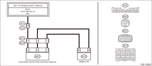
Wiring diagram:
Occupant detection system Occupant Detection System > WIRING DIAGRAM">
| STEP | CHECK | YES | NO |
1.CHECK DTC.
Read the DTC of the occupant detection system. Read Diagnostic Trouble Code (DTC) > OPERATION">
Is any of DTC B1760, B1761, B1771 and B1795 detected?
Perform the diagnosis according to DTC.
Diagnostic Procedure with Diagnostic Trouble Code (DTC) > DTC B1650 OCCUPANT DETECTION SYSTEM MALFUNCTION">Go to Step 2.
2.CHECK POOR CONTACT OF CONNECTORS.
Check for poor contact of the connectors between the occupant detection control module and airbag control module.
Is there poor contact?
When the connector is not fully connected, reconnect the connector correctly. Replace the faulty harness if the connector is faulty. (Replace the airbag rear harness along with body harness. Or replace the occupant detection harness (seat harness).)
Diagnostic Procedure with Diagnostic Trouble Code (DTC) > DTC B1650 OCCUPANT DETECTION SYSTEM MALFUNCTION">Go to Step 3.
3.CHECK AIRBAG REAR HARNESS.
1) Turn the ignition switch to OFF, disconnect the battery ground cable, and wait for 60 seconds or more.
2) Disconnect the connectors (AB59) and (AB53) under the passenger’s seat.
3) Disconnect the connectors (AB6, AB17, AB18) from the airbag control module, and connect the connector (1AG) in the test harness AG to connectors (AB6, AB17, AB18).
4) Connect the connector (1AP) in the test harness AP to the connector (AB53).
5) Measure the resistance between connector (6AG) in the test harness AG and connector (2AP) in the test harness AP.
Connector & terminal
(6AG) No. 9 — (2AP) No. 2:
(6AG) No. 11 — (2AP) No. 1:
Is the resistance less than 10 ??
Diagnostic Procedure with Diagnostic Trouble Code (DTC) > DTC B1650 OCCUPANT DETECTION SYSTEM MALFUNCTION">Go to Step 4.
Replace the airbag rear harness along with body harness.
4.CHECK AIRBAG REAR HARNESS.
Measure the resistance between connector (6AG) in the test harness AG and chassis ground.
Connector & terminal
(6AG) No. 9 — Chassis ground:
(6AG) No. 11 — Chassis ground:
(6AG) No. 9 — (6AG) No. 11:
Is the resistance 1 M? or more?
Diagnostic Procedure with Diagnostic Trouble Code (DTC) > DTC B1650 OCCUPANT DETECTION SYSTEM MALFUNCTION">Go to Step 5.
Replace the airbag rear harness along with body harness.
5.CHECK OCCUPANT DETECTION HARNESS.
1) Turn the ignition switch to ON.
2) Measure the voltage between connector (2AP) in the test harness AP and chassis ground.
Connector & terminal
(2AP) No. 3 (+) — Chassis ground (–):
Is the voltage 10 V or more?
Replace the occupant detection harness (seat harness). If defective is not improved, replace the occupant detection system (seat cushion & frame assembly), and then the airbag control module in this order. Front Seat > DISASSEMBLY">
Check the battery voltage and fuse. If there is no fault, replace the airbag rear harness together with body harness.

 Dtc b1655 front buckle switch rh failure
OCCUPANT DETECTION SYSTEM (DIAGNOSTICS) > Diagnostic Procedure with Diagnostic Trouble Code (DTC)DTC B1655 FRONT BUCKLE SWITCH RH FAILUREDiagnosis start condition:Ignition voltage is 8 V to 16 V.DT ...
Other materials:
Removal
MECHANICAL(H4DO) > Chain CoverREMOVALNOTE:When replacing a single part, perform the work with the engine assembly installed to body.1. When working on the vehicleNOTE:When working on the vehicle, perform the following steps also.(1) Remove the radiator. Radiator > REMOVAL">(2) Remove ...
Dtc b1623 side airbag sensor rh initialization error
AIRBAG SYSTEM (DIAGNOSTICS) > Diagnostic Chart with Trouble CodeDTC B1623 SIDE AIRBAG SENSOR RH INITIALIZATION ERRORDiagnosis start condition:Ignition voltage is 10 V to 16 V.DTC detecting condition:• Open or short circuit in harness of side sensor bus (RH)• Side airbag sensor (RH) an ...
Dtc p2122 throttle/pedal position sensor/switch "d" circuit low
ENGINE (DIAGNOSTICS)(H4DO) > Diagnostic Procedure with Diagnostic Trouble Code (DTC)DTC P2122 THROTTLE/PEDAL POSITION SENSOR/SWITCH "D" CIRCUIT LOWDTC detecting condition:Immediately at fault recognitionTrouble symptom:• Improper idling• Poor driving performanceCAUTION:After ...
