Subaru Crosstrek Service Manual: Installation
LUBRICATION(H4DO) > Oil Pan
INSTALLATION
1. OIL PAN
1. Apply liquid gasket to the mating surface of the oil pan upper as shown in the figure, and install the oil pan.
NOTE:
• Before applying liquid gasket, degrease the old liquid gasket seal surface of the oil pan and the oil pan upper.
• Use a new oil pan seal ring.
• Install within 5 min. after applying liquid gasket.
Liquid gasket:
THREE BOND 1217G (Part No. K0877Y0100), THREE BOND 1217H or equivalent
Liquid gasket applying diameter:
5±1 mm (0.1969±0.0394 in)
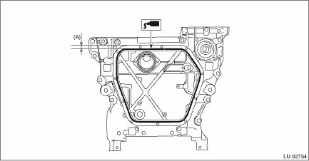
(A) | 7.5 mm (0.295 in) |
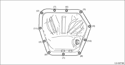
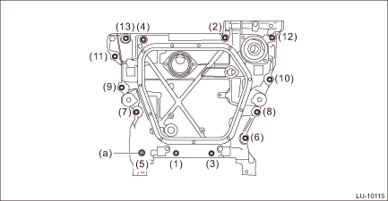
2. Tighten the bolts to install the oil pan to the oil pan upper in the numerical order.
Tightening torque:
6.4 N·m (0.7 kgf-m, 4.7 ft-lb)
3. Install the front exhaust pipe. Front Exhaust Pipe > INSTALLATION">
4. Install the under cover. Front Under Cover > INSTALLATION">
5. Lower the vehicle.
6. Connect the battery ground terminal. NOTE">
7. Refill the engine oil. Engine Oil > REPLACEMENT">
2. OIL PAN UPPER
1. Attach the clutch housing cover to the oil pan upper. (MT model)
2. Install the O-ring to the cylinder block.
NOTE:
Use new O-rings.
3. Attach the stud bolts to the oil pan upper.
4. Attach the oil strainer to the oil pan upper.
NOTE:
Use new O-rings.
5. Attach the baffle plate to the oil pan upper.
Tightening torque:
T1: 5 N·m (0.5 kgf-m, 3.7 ft-lb)
T2: 6.4 N·m (0.7 kgf-m, 4.7 ft-lb)
T3: 10 N·m (1.0 kgf-m, 7.4 ft-lb)
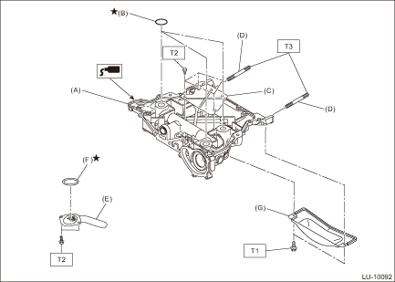
(A) | Oil pan upper | (B) | O-ring | (C) | Baffle plate |
(D) | Stud bolt | (E) | Oil strainer | (F) | O-ring |
(G) | Clutch housing cover (MT model) |
6. Apply liquid gasket to the mating surface of the oil pan upper as shown in the figure, and install the oil pan upper to the cylinder block.
NOTE:
• Before applying liquid gasket, degrease the old liquid gasket seal surface of the oil pan upper and the cylinder block.
• Install within 5 min. after applying liquid gasket.
• Apply liquid gasket 1.5 mm (0.0591 in) outside from the chamfer surface. However, application of liquid gasket on the chamfer surface around the bolt hole is allowed.
Liquid gasket:
THREE BOND 1217G (Part No. K0877Y0100), THREE BOND 1217H or equivalent
Liquid gasket applying diameter:
5±1 mm (0.1969±0.0394 in)
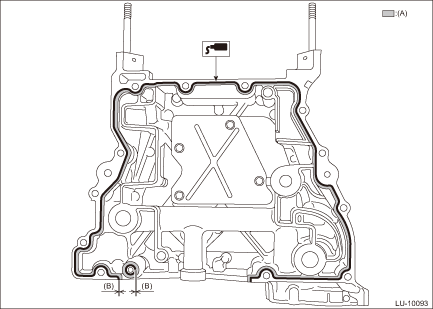
(A) | Chamfer surface | (B) | 1.5 mm (0.0591 in) |
7. Tighten the bolts to secure the oil pan upper to the cylinder block in the numerical order.
NOTE:
• Install the bolt (a) shown in the figure using TORX® bit T45.
• After tightening, if the liquid gasket is squeezed out onto the seal surface of the chain cover, completely remove any squeezed-out liquid gasket.
Tightening torque:
18 N·m (1.8 kgf-m, 13.3 ft-lb)
8. Install the oil level switch. Oil Level Switch > INSTALLATION">
9. Install the oil pan. Oil Pan > INSTALLATION">
10. Install the chain cover. Chain Cover > INSTALLATION">
11. Install the water pipe assembly. Water Pipe Assembly > INSTALLATION">
12. Install the thermostat cover. Thermostat > INSTALLATION">
13. Install the water pump. Water Pump > INSTALLATION">
14. Install the engine to the vehicle. Engine Assembly > INSTALLATION">
15. Refill the engine oil. Engine Oil > REPLACEMENT">
 Removal
LUBRICATION(H4DO) > Oil PanREMOVAL1. OIL PAN1. Disconnect the ground cable from battery. NOTE">2. Lift up the vehicle.3. Remove the under cover. Front Under Cover > REMOVAL">4. ...

Other materials:
Dtc b28b5 +b circuit open
EyeSight (DIAGNOSTICS) > Diagnostic Procedure with Diagnostic Trouble Code (DTC)DTC B28B5 +B CIRCUIT OPENDetected when there is an open circuit in power supply line.NOTE:Refer to DTC B2814 for diagnostic procedure. Diagnostic Procedure with Diagnostic Trouble Code (DTC) > DTC B2814 POWER SUPP ...
BSD/RCTA approach indicator light
BSD/RCTA approach indicator light
It is mounted on each side of the outside
mirrors.
The indicator light will illuminate when a
vehicle approaching from behind is detected.
The indicator light will flash to warn the
driver of dangers under the following
conditions.
While the indic ...
Starting engine
WARNING
There are some general precautions
when starting the engine.
Carefully read the precautions
described in "General precautions
when starting/stopping engine"
F7-9.
If the indicator on the pushbutton
ignition switch flashes in
green after the engine has
started, never dri ...
